Table of Contents
Advertisement
Quick Links
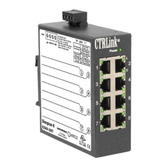
EISwitch
A Line of Fixed-Port Industrial Ethernet 10/100 Mbps Switches
INTRODUCTION
The EIS series — Ethernet Interconnect Switch in the CTRLink
solution for those industrial applications requiring a larger network diameter and greater
throughput. The EIS series becomes an essential element of the control strategy.
Classified as switching hubs, each device segments the Ethernet network into
separate collision domains. The EIS8-100T offers eight ports of expansion via
twisted-pair cabling. Four models offer fibre ports when greater distance or
galvanic isolation is required: The EIS6-100T/FC and EIS6-100T/FT
accommodate a fibre backbone via two fibre ports and offer four twisted-pair
ports for local drops. The EIS5-100T/FC and EIS5-100T/FT provide one fibre
port to terminate a fibre link and four local ports of twisted-pair. Each fibre
model also has an "–FCS" transceiver option for single-mode fibre.
Each switch functions as a "bridge" between the various data links — creating a
larger network diameter than can be achieved with repeating hubs. To optimise
speed and throughput, some functions are automatically negotiated:
Each twisted-pair port automatically optimises its data rate to 10 Mbps or
100 Mbps. The data rate of fibre ports is fixed at 100 Mbps.
Each port negotiates flow control — supporting the PAUSE function for full-
duplex links, and using the backpressure scheme for half-duplex segments.
The switch learns the ports of devices by reading Ethernet frames and noting
source addresses. It then creates and maintains a table of addresses and port
assignments by which traffic is restricted to only those ports party to a data
exchange. This allows other data to be simultaneously exchanged on other
ports—with improved throughput. If a broadcast, multicast, or unicast
transmission to an unknown destination arrives at a port, all other ports receive
the transmission. As an option for reduced data latency, cut-through operation
can be selected instead of store-and-forward operation.
The switch front-panel features one LED to warn of network
loops and LEDs for link status, port activity, and data rate of
each port. All units operate from low-voltage AC or DC power
and are DIN-rail mountable
CONTEMPORARY
INSTALLATION GUIDE
C
O
NTR LS
O
R
family — provides a
®
INDUSTRIAL
CONTROL
EQUIPMENT
4EA4
Advertisement
Table of Contents

Related Manuals for Contemporary Controls CTRLink EIS Series


Summary of Contents for Contemporary Controls CTRLink EIS Series
- Page 1 EISwitch A Line of Fixed-Port Industrial Ethernet 10/100 Mbps Switches INSTALLATION GUIDE INTRODUCTION The EIS series — Ethernet Interconnect Switch in the CTRLink family — provides a ® solution for those industrial applications requiring a larger network diameter and greater throughput.
- Page 2 TRADEMARkS Contemporary Controls, ARC Control, ARC DETECT, BASautomation, EXTEND-A-BUS, RapidRing, and CTRLink are trademarks or registered trademarks of Contemporary Control Systems, Inc. Specifications are subject to change without notice. Other product names may be trademarks or registered trademarks of their respective companies. BACnet is a registered trademark of the American Society of Heating, Refrigeration, and Air-Conditioning Engineers, Inc.
-
Page 3: Specifications
SPECIFICATIONS Electrical LED Indicators INPUT SWITCh EACh PORT Power—green Link/Data—green Voltage: 10–36 V 8–24 V Loop Detect—red Data Rate—yellow Power: 6 VA Frequency: 47–63 Hz Regulatory Compliance Environmental CFR 47, Part 15 Class A Operating temperature: 0°C to +60°C UL 508 Listed Device Storage temperature: –40°C to +85°C (intended for use with Class 2 circuits only) Humidity, non-cond.:... -
Page 4: Installation
INSTALLATION The EISwitch is intended to be panel-mounted in an industrial enclosure or wiring closet with two #8 pan-head screws (not provided). An optional DIN-rail mounting kit is also available. Refer to the mechanical specification for details. Cabling Considerations When attaching cables to the EISwitch, Table 1 should be considered. Table 1 —... - Page 5 Configuring Switches in Fibre Cable Networks The EIS series includes two types of devices which accommodate different fibre backbone situations. One device provides connectivity from one link to another via dual fibre ports. The other device terminates the backbone with a single fibre port. Each type of device offers four RJ-45 ports for attaching local equipment.
- Page 6 Powering The EISwitch requires low-voltage power — AC or DC — via a four-pin removable keyed connector. Consult the specifications for power requirements. The various power options are explained below. NOTE: This device is intended for use with Class 2 circuits. DC Powered The EISwitch accepts a voltage range of 10–36 VDC and draws a current value commensurate with 5-watt power consumption.
- Page 7 AC Powered The EISwitch can be powered by an AC voltage in the range of 8–24 V capable of delivering 5 VA of apparent power. Two auxiliary power supplies are available: The AI-XFMR is for use with 120 VAC. The AI-XFMR-E is for use with 230 VAC.
-
Page 8: Operation
OPERATION Switching The EISwitch uses an 8K-address look-up table augmented with 128 entries of Content Addressable Memory. An address-hashing algorithm is used to update the table. Addresses are aged in 215-322 seconds. Runt packets (less than 64 bytes) are always discarded. In store-and-forward mode, oversize packets (greater than 1536 bytes) are discarded. -
Page 9: External Leds
External LEDs PWR (green) Power — Glows when power is supplied to the EISwitch. Loop Detect — Glows when a wiring loop exists as LD (red) described in the section entitled Loop Detection. LINK (green) Link — Each port has one of these LEDs which glows to indicate that a valid Ethernet link has been established. - Page 10 Figure 7 illustrates all installed jumper headers, including five used only for factory testing. These are JP3, JP4, JP13 which have no jumpers installed — and JP1, JP2 which have jumpers that must be left in their default positions. If viewed as shown in Figure 7, the user-adjustable jumpers may be set according to Tables 2 and 3 —...
-
Page 11: Internal Leds
Internal LEDs The data flow of each 100BASE-TX port is auto-negotiated. When such a channel is in full-duplex mode, its associated LED will glow. In half-duplex mode, its LED will be off — but will flash during a data collision. The data flow of each 100BASE-FX port is set by a jumper (see Table 3). -
Page 12: Warranty
Technical Support. WARRANTy Contemporary Controls (CC) warrants its new product to the original purchaser for two years from the product shipping date. Product returned to CC for repair is warranted for one year from the date that the repaired product is shipped back to the purchaser or for the remainder of the original warranty period, whichever is longer.
Need help?
Do you have a question about the CTRLink EIS Series and is the answer not in the manual?
Questions and answers