
Subscribe to Our Youtube Channel
Related Manuals for finder 7M Series


Summary of Contents for finder 7M Series
- Page 1 7M USER’S MANUAL SERIES OF SINGLE PHASE METERS 7M.24.8.230.0001 7M.24.8.230.0010 7M.24.8.230.0110 7M.24.8.230.0210 7M.24.8.230.0310...
- Page 2 7M User’s Manual 7M SERIES SINGLE-PHASE ELECTRICAL ENERGY METER User and Installation manual...
- Page 3 FINDER S.p.A assumes no responsibility in connection with installation and use of the product. If there is any doubt regarding installation and use of the system in which the device is used for measuring or supervision, please contact a person who is responsible for installation of such system.
- Page 4 7M User’s Manual Used symbols on devices’ housing and labels SYMBOL EXPLANATION WARNING Indicates situations where careful reading of this manual is required and following requested steps to avoid potential injury is advised. Double insulation in compliance with the EN 61010−1: 2010 standard. Compliance of the product with directive 2002/96/EC, as first priority, the prevention of waste electrical and electronic equipment (WEEE), and in addition, the reuse, recycling and other forms of recovery of such wastes so as to reduce the...
-
Page 5: Table Of Contents
SOMMARIO 7M User’s Manual 1. BASIC DESCRIPTION AND OPERATION 1.1 Description of the device 1.2 Single-phase energy meters application 1.3 Types of 7M.24 Energy meters 1.4 Main features 2. CONNECTION 2.1 Mounting 2.2 Electrical connection 3. FIRST STEPS 3.1 Display of device info 3.2 Lcd user interface 4. -
Page 6: Basic Description And Operation
7M User’s Manual 1. BASIC DESCRIPTION AND OPERATION 1.1 Description of the device The single-phase energy meters 7M.24 are intended for energy measurements in single-phase electrical power networks and can be used in residential, industrial and utility applications. Meters measure energy directly in 2-wire networks according to the principle of fast sampling of voltage and current signals. -
Page 7: Single-Phase Energy Meters Application
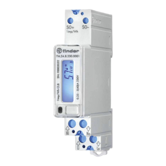
7M User’s Manual 1.2 Single-phase energy meters application 7M.24 is a single phase energy meter that can be equipped with optical (IR) communication port on the side as a standard depending on model. Meter can be equipped: • S0 output (pulse output) is intended for connection to the devices that are checking and monitoring consumed energy. •... -
Page 8: Main Features
7M User’s Manual 1.4 Main features • Single-phase direct connected DIN-rail mounting meters • Active energy class B for MID approved types according to EN 62053-21 and class 1 for other types (non-MID version) according to EN 50470-3 • Reactive energy Class 2 according to EN 62053-23 •... -
Page 9: Connection
Connection shall therefore be performed ONLY by a qualified person using an appropriate equipment. Finder S.p.A. does not take any responsibility regarding the use and connection. If any doubt occurs regarding connection and use in the system which device is intended for, please contact a person who is responsible for such installations. - Page 10 7M User’s Manual MARK MEANING Line input Neutral input Line output Neutral output Figure 3: Electrical diagram 230 VAC Figure 4: Connection diagram for pulse output Figure 5: Connection diagram for M-Bus option Figura 6: Connection diagram for RS485 communication...
- Page 11 7M User’s Manual 2.2.1 Communication connection There are multiple options for communication available for interaction with the outside world. • IR communication module (option) using the MODBUS. It can be used for setting and testing the meter using USB adapter •...
-
Page 12: First Steps
7M User’s Manual 3. FIRST STEPS Programming a single phase energy meter 7M.24 is very transparent and user friendly. Numerous settings are organized in groups according to their functionality. 3.1 Display Measured data is presented on LCD. Display scrolls automatically. Displayed quantities and scroll time can be set via communication via mobile app using NFC. -
Page 13: Lcd User Interface
7M User’s Manual 3.2 LCD User Interface After the electrical connection, the display shows a segment check screen, software version screen and check sum screen in a period of five seconds. After that is visible the basic display that shows the E1 MID counter for active energy (is possible that the display will show small amount of energy measured and/or other parameters depending on the test done in the production line as per request by MID production procedure). - Page 14 7M User’s Manual 3.2.1 Cap touch self calibration process In a reported fixed 64s interval the average, minimum and maximum value of the cap touch sensor is calculated. If the conditions are stable (without interruptions) then the average value of the cap touch sensor is used as a reference value. If the new reference value deviates sufficiently from the permanently stored value, it is permanently saved.
- Page 15 7M User’s Manual Table 1: counter description with Obis-coded and “Finder-coded” REGISTER DESCRIPTION E1 TO E4 OBIS CODE LETTER DESCRIPTION CODE Active energy Q1+Q4 – all tariffs 1.8.0 A.I.0 Active energy Q2+Q3 – all tariffs 2.8.0 A.E.0 Active absolute energy– all tariffs 15.8.0...
- Page 16 7M User’s Manual 3.2.3 Actual measured quantities The number on the screen shows the actual value of the measured quantity (P-W, Q-var, S, PF, U, f and I). Furthermore the screen shows the direction of active energy flow (import/export = (/)) and reactance (inductive/capacitive = L/C). ACTIVE POWER REACTIVE POWER APPARENT POWER...
- Page 17 7M User’s Manual 3.2.4 Initial display menu structure The display menu is entered by touching the capacitive button for more than one second. Blinking of the screen indicates that. Use short touches to move through the main menu. If the capacitive button is not used for more than one minute, the initial page will be shown automatically.
- Page 18 7M User’s Manual Software Check sum: A checksum is a small-sized datum derived from a block of digital data for the purpose of detecting errors that may have been introduced during its transmission or storage. Screen 1: Measurement module Check-sum Screen 2: Functional module Check-sum Parameters Check sum:...
- Page 19 7M User’s Manual MID relevant counters: Screen 1: MID unlock counter Screen 2: FW upgrade counter (measuring mode) Digits check menu: 3.2.4.3 Set menu 3.2.4.3.1 Set sub-menus Led test mode (Led tSt): This function shall be used only for testing purposes during type testing and metrological verification of the meters.
- Page 20 7M User’s Manual TEST MODES: Normal – 1000 imp/kWh, counter resolution 100 Wh/100 varh P fast (Test mode P Fast) – 100000 imp/kWh, counter resolution 1 Wh/1 varh P F cnt (Test mode P Fast – counter only) – 1000 imp/kWh, counter resolution 1 Wh/1 varh P test (Test mode P) –...
- Page 21 7M User’s Manual Communication menu (when in COMM menu, short touches move user through it): Communication menu is available at M-bus and RS485 option and can be used for setting communication parameters (communication addresses, baud rate, parity and stop bits) M-bus setting menu: 7M with MBus communication protocol must be configured using the submenu “COMM”...
- Page 22 7M User’s Manual Baud rate: RS485 (Modbus) setting menu: If you stop using short touches on a certain screen, the screen with the parameter value is shown and it starts cycling automatically. With long touch you can enter the setting mode. Address: When the character is blinking, one can scroll through numbers using short touches.
- Page 23 7M User’s Manual 3.2.4.3 Reset menu When in reset menu, short touches move user through it, allowing her/him to select a dedicated menu. With long touch, all counters or single counter can be chosen. Above an example of how reset counter number 7, E07. For final execution, additional confirmation of reset is necessary. 3.2.4.3 Error display In case the meter detects error in firmware or parameter check sum, the Error screen with the decimal value of the first three bits is displayed after each cycle of the displayed quantities.
-
Page 24: Technical Data
7M User’s Manual 4. TECHNICAL DATA 4.1 Accuracy 4.2 Mechanical characteristics of input TERMINALI 1.5 mm ... 10mm Capacità serraggio morsetti *Lunghezza del puntalino deve essere12 mm. con cavo flessibile / (rigido): Spellatura fino a 14 mm Viti di connessione: M3.5 Ingressi principali Coppia massima di serraggio:... -
Page 25: Electrical Characteristics Of Input
7M User’s Manual 4.3 Electrical characteristics of input CARATTERISTICHE ELETTRICHE 7M.24 Tipo (connessione) monofase (1b) Corrente di riferimento (I ref ) Corrente massima (I max ) 40 A Corrente minima (I min ) 0.25 A Corrente di transizione (I tr ) 0.5 A Corrente di avviamento (I st ) 20 mA... - Page 26 7M User’s Manual TERMINALI Tipo Optocoupler - open collector switch Impulsi per kWh 1 imp/Wh - (1000 imp/kWh) Durata impulso 32 ms ± 2 ms Uscita impulsiva (opzionale) Tensione di alimentazione DC 27 V max Massima corrente commutabile 27 mA max Standard EN 62053-31 (A&B) Tipo...
-
Page 27: Safety And Ambient Conditions
7M User’s Manual 4.4 Safety and ambient conditions According to standards for indoor active energy meters. Temperature and climatic condition according to EN 62052-11. Protezione polvere/acqua IP50 (per IP51 deve essere installato in un cabinet opportuno) Grado di protezione IP IP20 Temperatura ambiente di utilizzo –25 °C - +55 °C (umidità... -
Page 28: Eu Directives Conformity
7M User’s Manual 4.5 Eu directives conformity EU Directive on Measuring Instruments 2014/32/EU EU Directive on EMC 2014/30/EU EU Directive on Low Voltage 2014/35/EU EC Directive WEEE 2002/96/EC EU DIRECTIVE RED 2014/53/EU 4.6 Dimensions Dimensional drawing... -
Page 29: Appendices
7M User’s Manual 5. APPENDICES PLEASE NOTE This chapter is a subject of change. Please download from www.findernet.com the dedicated guide for Modbus and M-Bus communication protocol 5.1 MODBUS communication protocol Modbus protocol enables operation of device on Modbus networks. For 7M.24 with serial communication the Modbus protocol enables multi drop communication via RS485 communication. - Page 30 7M User’s Manual Request frame Starting Register Register Count Slave Address Function Code Response frame Register Data Slave Address Function Code Byte Count Request-response cycle example Address number of slave: 21 Function code: 04 --> 30000 Starting register HI…LO: 00…6B -->...
-
Page 31: M-Bus
7M User’s Manual 5.2 M-Bus The M-Bus interface fully complies with M-Bus European standard EN13757-2. The entire communication is ensured with 8 Data Bits, Even Parity, 1 Stop Bit and a Baud Rate from 300 to 9600 Bauds. Communication settings Default communication settings are: 2400, 8, E, 1 primary address 0 and secondary address is set to serial number of device. - Page 32 7M User’s Manual M-Bus Telegram Total Energy counters 0, 1, 2, 3 Energy counters could represent: +/- active energy, +/-reactive energy or apparent energy and one of 4-th tariff. DIFE DIFE VIFE VIFE VIFE DATA xx.xx.xx.xx none none none none none none none...
-
Page 33: Obis Code
7M User’s Manual Current Total (A) Total current as 32 bit x 10 (9-12) DIFE VIFE VIFE DATA xx.xx.xx.xx System frequency (Hz/1000) Contains the line frequency 32-bit integer in mHz DIFE DIFE VIFE VIFE VIFE DATA xx.xx.xx.xx Voltages (V) Voltage as 32 bit x 10 (7-9) DIFE VIFE... - Page 34 7M User’s Manual Reactive energy register 3.8.0 Positive reactive energy (Q+) total [kvarh] 3.8.1 Positive reactive energy (Q+) in tariff T1 [kvarh] 3.8.2 Positive reactive energy (Q+) in tariff T2 [kvarh] 3.8.3 Positive reactive energy (Q+) in tariff T3 [kvarh] 3.8.4 Positive reactive energy (Q+) in tariff T4 [kvarh] 4.8.0...
- Page 35 findernet.com...
Need help?
Do you have a question about the 7M Series and is the answer not in the manual?
Questions and answers