
Related Manuals for finder 7M.38.8.400.0112


Summary of Contents for finder 7M.38.8.400.0112
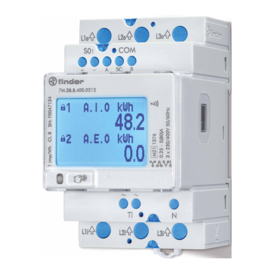
- Page 1 USER’S MANUAL 7M SERIES OF THREE-PHASE METERS 7M.38.8.400.XXXX: 7M.38.8.400.0112 7M.38.8.400.0212 7M.38.8.400.0312...
- Page 2 User’s Manual 7M THREE-PHASE ELECTRICAL ENERGY METER USER AND INSTALLATION MANUAL...
- Page 3 Installation and use of a device also includes handling with dangerous currents and voltages therefore should be installed, operated, serviced and maintained by qualified personnel only. FINDER S.p.A assumes no responsibility in connection with installation and use of the product.
- Page 4 User’s Manual 7M USED SYMBOLS ON DEVICES’ HOUSING AND LABELS SYMBOL EXPLANATION Three-phase 4-wire connection (3L+N) Three-phase 3-wire 3 system connection (3L) Three-phase 3-wire 2 system connection (3L-2I Aron connection) Single-phase connection (L+N). WARNING Indicates situations where careful reading of this manual is required and following requested steps to avoid potential injury is advised Double insulation in compliance with the EN 61010−1: 2010 standard NFC communication...
- Page 5 User’s Manual 7M SYMBOL EXPLANATION Modbus communication MBus communication Compliance of the product with directive 2002/96/EC, as first priority, the prevention of waste electrical and electronic equipment (WEEE), and in addition, the reuse, recycling and other forms of recovery of such wastes so as to reduce the disposal of waste.
- Page 6 User’s Manual 7M TABLE OF CONTENTS BASIC DESCRIPTION AND OPERATION page - 6 INTRODUCTION page - 6 DESCRIPTION OF THE DEVICE page - 6 THREE-PHASE ENERGY METERS APPLICATION page - 7 MAIN FEATURES page - 7 TYPE DIFFERENCES page - 8 CONNECTION page - 9 MOUNTING...
- Page 7 User’s Manual 7M BASIC DESCRIPTION AND OPERATION The following chapter presents basic information about a three-phase energy meter 7M.38.8.400.xxxx required to understand its purpose, applicability and basic features connected to its operation. In this chapter you will find: • INTRODUCTION •...
- Page 8 (option) THD of voltage THD of current • 2nd multifunction pulse output (valid only for 7M.38.8.400.0112) • RS485 Serial communication (valid only for 7M.38.8.400.0212) • NFC (option) enables an easy setting and downloading meter data via mobile app •...
- Page 9 User’s Manual 7M TYPE DIFFERENCES Different type differ on functionality and equipment as shown in the following table. General hardware features 7M.38.8.400.0112 7M.38.8.400.0212 7M.38.8.400.0312 MID approval Pulse output S0 Pulse output S0 – – Tariff input 70°C display Infrared (optical) communication - IR MODBUS comm.
- Page 10 Both the use and connection of the device includes handling with dangerous currents and voltages. Connection shall therefore be performed ONLY by a qualified person using an appropriate equipment. FINDER S.p.A, does not take any responsibility regarding the use and connection.
- Page 11 User’s Manual 7M ELECTRICAL CONNECTION WARNING Wrong or incomplete connection of voltage or other terminals can cause non-operation or damage to the device. Installation must be carried out and inspected by a specialist or under his supervision. When working on the meter, switch off the mains voltage! It is recommended to use 3x80 A fuse for the line protection. Meter is used for direct connection into the three-phase four-wire or three-wire networks.
- Page 12 User’s Manual 7M Figure 3: Three-phase 4-wire connection diagram (3L+N) Figure 4: Three-phase 3-wire 3 system connection diagram (3L) Figure 5: Three-phase 3-wire 2 system connection diagram (3L-2I)
- Page 13 User’s Manual 7M Figure 6: Single.-phase connection diagram L+N Figure 7: Connection diagram of S0 output, impulse counter, impulse counter or controller and tariff clock Figure 8: Connection diagram of S0 output, impulse counter, RS485 - Modbus and tariff clock...
- Page 14 User’s Manual 7M Figure 9: Connection diagram of S0 output, impulse counter, M - bus and tariff clock AUXILIARY CIRCUIT CONNECTION For communication with outside world multiple manners are used: • IR communication module (option) using MODBUS protocol. It can be used for setting and testing the meter using USB adapter. •...
- Page 15 User’s Manual 7M FIRST STEPS Programming a three-phase electrical energy meter 7M.38.8.400.xxxx is very transparent and user friendly. Numerous settings are organized in groups according to their functionality. In this chapter you will find basic programming steps: KEYBOARD NAVIGATION LCD USER INTERFACE CALIBRATION AND SETTING PARAMETERS FREEZE COUNTERS KEYBOARD NAVIGATION...
- Page 16 User’s Manual 7M CAPACITIVE TOUCH SELF CALIBRATION PROCESS In a reported fixed 64s interval the average, minimum and maximum value of the capacitive touch sensor is calculated. If the conditions are stable (without interruptions) then the average value of the capacitive touch sensor is used as a reference value.
- Page 17 User’s Manual 7M Legally relevant non-resettable registers are designated with letters 1 to 4 after the lock sign, while legally non-relevant resettable registers are designated with 01 to 16. The code is specified in table 4 and table 5. REGISTER DESCRIPTION E1 TO E4 OBIS CODE LETTER DESCRIPTION CODE Active energy Q1+Q4 –...
- Page 18 User’s Manual 7M INITIAL DISPLAY MENU STRUCTURE The following is a main menu divided into several sub-menus (ESC, Measurements, Info, Settings, Resets, Installation). MAIN MENU: MEASUREMENTS INFO SETTINGS RESETS INSTALLATION www.findernet.com / Temperature 27 °C Long-touch ESC, the screen holds on to the chosen measurement on default mode. The mode could be changed in Fi-MIS software, to counter n1 or to cycling mode (cycling between measurements).
- Page 19 User’s Manual 7M VOLTAGE Long-touch Voltage to observe the phase voltage, phase to phase voltage, voltage angle, average values of phase voltage, and average values of phase to phase voltage. CURRENT Long- touch Current to observe the phase current, and average current. POWER Long- touch Power to observe the power (active, reactive, apparent), phase power (active, reactive, apparent).
- Page 20 User’s Manual 7M FREQUENCY ENERGY Long- touch Energy to observe the measured energy. Two different types of energy registers are shown (resettable and non-resettable). Disabled energy counters are not shown on the screen. The resettable energy counter (Non-MID meters) can be reset, while the non-resettable (the symbol of lock representing it) has been measuring the quantity continuously.
- Page 21 User’s Manual 7M CUSTOM Long- touch Custom to observe the measurements of phase one, measurements of phase two, measurements of phase three and custom measurements. OVERVIEW Long- touch Overview to observe the custom screens. LIMITS Long- touch Limits to observe the limits set in settings (see chapter 4 Settings, Limits). Long- touch ESC to return to the measurements menu.
- Page 22 User’s Manual 7M DISPLAY OF DEVICE INFO Long- touch Info to view informations about the energy meter (name, date, hour, firmwhare/technical informations, informations of locking, error informations). Instrument info abbreviations: SN: serial number MID: Version and CRC of Part 2, U: upgrade counter FUN: Version and CRC of Part 2, L: unlock counter HW: Hardware version, m.
- Page 23 User’s Manual 7M GENERAL GENERAL Language <= Settings Long- touch General, the sub-menu is entered (ESC, Language). Long- touch ESC to return to the settings menu. Long- touch Language to set language (the options are shown in pictures below). Short-touch to chose the requested language, then long-touch ESC to confirm it. DATE AND TIME Long- touch Date and time, the sub-menu is entered (ESC, Date, Time.
- Page 24 User’s Manual 7M COMMUNICATION Communication menu is available at M-bus and MODBus RS485 option (7M.38.8.400.0312 and 7M.38.8.400.0212) and can be used for setting communication parameters (communication addresses, bits per second, parity and stop bits). Long-touch Communication, the sub-menu is entered (ESC, Device address, Bits per second, Parity, Stop bits).
- Page 25 User’s Manual 7M Long-touch LCD, the sub-menu is entered (ESC, Contrast, Backlight, Backlight time off, LCD scroll interval). Long-touch ESC to return to the settings menu Long-touch Contrast to set the value of the contrast of the screen (from -10 to 10). Long-touch the selected value to save the settings.
- Page 26 User’s Manual 7M SECURITY Long-touch Security, the sub-menu is entered (ESC, Password level 1, Password level 2, Lock instrument, unlock instrument). Long-touch ESC LCD returns to the settings menu. A password consists of four letters taken from the British alphabet from A to Z. When setting a password, only the letter being set is visible while the others are covered with •...
- Page 27 User’s Manual 7M DISPLAY OF DEVICE RESETS Long-touch Reset, the sub-menu is entered (ESC, Energy counters, Reset alarm output). RESETS Energy counters Reset alarm output <= Main menu ENERGY COUNTERS Long-touch Energy counters to chose the counter to reset (ESC, All energy counters, from energy counter C1 to C16). Longtouch ESC to return to the Resets.
- Page 28 User’s Manual 7M ERROR DISPLAY ON LCD If error is detected Error display appears on LCD after each cycle for 5 seconds. The first two bits are the summary description of CRC errors. The decimal value of first 3 Bits (0 ...7) is displayed as Error. The other bits are shown with 2 values: - Data CRC –...
- Page 29 User’s Manual 7M AUTO FREEZE INTERVAL REGISTER (41901) The purpose of the auto freeze interval register is to freeze energy meters in the same time interval, for example, every day. Set the certain auto freeze interval (in minutes). Maximum allowed value is 65535 minutes. Periodic synchronization is activated automatically after the entered interval.
- Page 30 User’s Manual 7M TECHNICAL DATA In following chapter all technical data regarding operation of a three-phase electrical energy meter is presented. • ACCURACY • MECHANICAL CHARACTERISTICS OF INPUT • ELECTRICAL CHARACTERISTICS OF INPUT • SAFETY AND AMBIENT CONDITIONS • EU DIRECTIVES CONFORMITY •...
- Page 31 User’s Manual 7M ELECTRICAL CHARACTERISTICS OF INPUT TERMINALS MAX. CONDUCTOR CROSS-SECTIONS Type (connection): three-phase (4u and 3u), single-phase (1b) Reference current I Maximum current ( I 80 A Minimum current (I 0.25 A Transitional current (I 0.5 A MEASURING INPUT Starting current: 20 mA Power consumption at I...
- Page 32 User’s Manual 7M SAFETY AND AMBIENT CONDITIONS According to standards for indoor active energy meters. Temperature and climatic condition according to EN 62052-11. DUST/WATER PROTECTION: IP50 (For IP51 it should be installed in appropriate cabinet.) OPERATING TEMPERATURE: –25 °C - +70 °C (non- condensig humudity) STORAGE TEMPERATURE: –40 °C - + 85°C ENCLOSURE:...
- Page 33 User’s Manual 7M EU DIRECTIVES CONFORMITY MID CERTIFIED METERS MID APPROVAL APPLIES TO NON-RESETTABLE ACTIVE ENERGY COUNTERS. EU DIRECTIVE ON MEASURING INSTRUMENTS 2014/32/EU EU DIRECTIVE ON EMC 2014/30/EU EU DIRECTIVE ON LOW VOLTAGE 2014/35/EU EU DIRECTIVE WEEE 2002/96/EC EU RED DIRECTIVE 2014/53/EU DIMENSIONS DIMENSIONAL DRAWING CONSTRUCTION...
- Page 34 Most common abbreviations and expressions are explained in the following table: TERM EXPLANATION MODBUS Industrial protocol for data transmission FI-MIS Setting Software for FINDER S.p.A instruments ETHERNET IEEE 802.3 data layer protocol Alternating quantity Pulse input module Infrared (optical) communication...
- Page 35 The Modbus table is subject to change without notice. For the latest and complete Modbus table please visit FINDER S.p.A web page. Communication operates on a master-slave basis where only one device (the master) can initiate transactions called ‘Requests’ .
- Page 36 User’s Manual 7M REQUEST FRAME Starting Register Register Count Slave Address Function Code HI LO HI LO LO HI 00 6B 00 02 RESPONSE FRAME Register Data Slave Address Function Code Byte Count HI LO HI LO LO HI FE 00 59 96 REQUEST- RESPONSE CYCLE EXAMPLE Address number of slave: 21 Function code: 04 –>...
- Page 37 User’s Manual 7M Contents Data Values / Dependencies Address Input Registers READ ONLY INFO 30000 Memory Reference READ ONLY INFO 30001 30008 Model Number T_Str16 30009 30012 Serial Number T_Str8 30013 Software Reference Software version 30014 Hardware Reference T_Str2 Hardware version 30015 Calibration voltage V/100...
- Page 38 User’s Manual 7M Contents Data Values / Dependencies Address Input Registers 30073 MID Setting Data CheckSum 30074 Setting Data CheckSum 30075 Software Checksum 30076 MID lock status unlocked locked 30077 30078 Calibration Time Stamp T_unix 30079 MID unlock counter 30080 FW upgrade counter 30081 Software Checksum HI...
- Page 39 User’s Manual 7M Contents Data Values / Dependencies Address Input Registers ACTUAL MEASUREMENTS 30101 Phase valid measurement Bit 0 Invalid measurement phase 1 Bit 1 Invalid measurement phase 2 Bit 2 Invalid measurement phase 3 30102 reserved 30103 30104 Run time seconds 30105 30106...
- Page 40 User’s Manual 7M 30174 angle between U2 and I2 30175 angle between U3 and I3 30181 Internal Temperature THD HARMONIC DATA 30182 U1 THD% 30183 U2 THD% 30184 U3 THD% 30188 I1 THD% 30189 I2 THD% 30190 I3 THD% I/O STATUS Bit 0..4 Group 1 Limit 1 ..
- Page 41 User’s Manual 7M Contents Data Values / Dependencies Address Input Registers ENERGY No Error (OK) Bit 0 Error Parameter CRC 30400 CheckSum Status Bit 1 Error Firmware CRC Bit 2 Error MID-lock Bit 3 Error phase module 1 CheckSum Bit 4 Error phase module 2 CheckSum Bit 5 Error phase module 3 CheckSum...
- Page 42 User’s Manual 7M Contents Data Values Address ENERGY 30446 Energy Counter 1 Exponent 30447 Energy Counter 2 Exponent 30448 Energy Counter 3 Exponent 30449 Energy Counter 4 Exponent 30450 Energy Counter 5 Exponent 30451 Energy Counter 6 Exponent 30452 Energy Counter 7 Exponent 30453 Energy Counter 8 Exponent 30454...
- Page 43 User’s Manual 7M Contents Data Values Address ENERGY 32480 32481 Run time T_float seconds 32482 32483 Reserved for Frequency (fast response) T_float 32484 32485 Uavg (phase to neutral) T_float 32486 32487 Uavg (phase to phase) T_float 32488 32489 T_float 32490 32491 Active Power Total (Pt) T_float...
- Page 44 User’s Manual 7M 32568 32569 CAP/IND P. F. Total (PFt) T_float 32570 32571 j1 (angle between U1 and I1) T_float 32572 32573 j2 (angle between U2 and I2) T_float 32574 32575 j3 (angle between U3 and I3) T_float 32576 32577 Power Angle Total (atan2(Pt,Qt)) T_float 32578...
- Page 45 User’s Manual 7M INTERVAL MEASUREMENTS Interval measurements are intended for data collection and synchronization of the time for data reading, trough the communication. The time interval of data reading is programmable, by default is one minute. The minimum and maximum measurements could be read within a given time interval. Contents Data Values / Dependencies...
- Page 46 User’s Manual 7M Contents Data Values / Dependencies Address Input Registers AVERAGE MEASUREMENTS THD HARMONIC DATA 35582 U1 THD% 35583 U2 THD% 35584 U3 THD% 35588 I1 THD% 35589 I2 THD% 35590 I3 THD% MAXIMUM MEASUREMENTS 35605 35606 Frequency 35607 35608 35609 35610...
- Page 47 User’s Manual 7M Contents Data Values / Dependencies Address Input Registers AVERAGE MEASUREMENTS 35675 j3 (angle between U3 and I3) 35681 Internal Temperature THD HARMONIC DATA 35682 U1 THD% 35683 U2 THD% 35684 U3 THD% 35685 U12 THD% 35686 U23 THD% 35687 U31 THD% 35688...
- Page 48 User’s Manual 7M Contents Data Values / Dependencies Address Input Registers AVERAGE MEASUREMENTS 35772 Power Angle Total (atan2(Pt,Qt)) 35773 j1 (angle between U1 and I1) 35774 j2 (angle between U2 and I2) 35775 j3 (angle between U3 and I3) 35781 Internal Temperature THD HARMONIC DATA 35782...
- Page 49 User’s Manual 7M 40030 Select Active Tariff Bit-0..7 Reset counter 1 .. 8 40031 Reset energy command register 1 65535 Bit-8...15 Reset counter 9 .. 16 40032 Reset energy command register 2 Bit-i Reset counter i+17 65535 INSTALATION SETTINGS Password to attempt 40051 40052 Instalation Password T_Str4 A…Z...
- Page 50 User’s Manual 7M 40178 LCD Custom screen 2 - Line 1 See OutTypes 40179 LCD Custom screen 2 - Line 2 See OutTypes 40180 LCD Custom screen 2 - Line 3 See OutTypes 40181 LCD Custom screen 3 - Line 1 See OutTypes 40182 LCD Custom screen 3 - Line 2...
- Page 51 User’s Manual 7M Address Contents Data Values P. Level COMMUNICATION 40202 Port 1: Device Adress (Modbus) Baud rate 1200 Baud rate 2400 Baud rate 4800 Baud rate 9600 40203 Port 1: Boud Rate Baud rate 19200 Baud rate 38400 Baud rate 57600 Baud rate 115200 1 Stop bit 40204...
- Page 52 User’s Manual 7M Address Contents Data Values P. Level ENERGY Tariff input 40401 Active Tariff 1..4 Tariff 1..4 5..6 Tariff 5..6 Common Energy Counter 40402 –3 Exponent 40403 40418 Reserved Evaluation of the sum of phases 40419 Total Energy Calculation Evaluation of individual phases Standard calculation...
- Page 53 User’s Manual 7M see Energy Counter n1 40426 Energy Counter n2 Configuration Configuration see Energy Counter n1 40427 Energy Counter n2 Exponent –3 Exponent see Energy Counter n1 40428 Energy Counter n2 Tarif Selector Tarif Selector see Energy Counter n1 40429 Energy Counter n3 Parameter Parameter...
- Page 54 User’s Manual 7M see Energy Counter n1 40451 Energy Counter 4 Exponent –3 Exponent see Energy Counter n1 40452 Energy Counter 4 Tarif Selector Tarif Selector see Energy Counter n1 40453 Energy Counter 5 Parameter Paramete see Energy Counter n1 40454 Energy Counter 5 Configuration Configuration...
- Page 55 User’s Manual 7M DATA TYPES DECODING Registers defined in the Modbus database will define data as one of the data types described in the following table: TYPE VALUE / BIT MASK DESCRIPTION Unsigned Value (16 bit) Example: 12345 stored as 12345 = 3039 (16) Signed Value (16 bit) Example: -12345 stored as -12345 = CFC7...
- Page 56 User’s Manual 7M TYPE VALUE / BIT MASK DESCRIPTION Time and Date (64 bit) bits # 63..56 1/100s 00 - 99 (BCD) bits # 55..48 Seconds 00 - 59 (BCD) bits # 47..40 Minutes 00 - 59 (BCD) T_Time bits # 39..32 Hours 00 - 24 (BCD) bits # 31..24 Day of month 01 - 31 (BCD)
- Page 57 User’s Manual 7M APPENDIX B: M-BUS The M-BUS interface fully complies with M-BUS European standard EN13757-2. The entire communication is ensured with 8 Data Bits, Even Parity, 1 Stop Bit and a Baud Rate from 300 to 9600 Bauds. COMMUNICATION SETTINGS Default communication settings are: 2400, 8, E, 1 primary address 0 and secondary address is set to serial number of device.
- Page 58 User’s Manual 7M RESET, RESTART M-BUS MC350 VIA PRIMARY/SECONDARY ADDRESS (SND_UD This Telegram reset/restarts M-BUS MC350. The M-BUS 7M.38.8.400.XXXX confirms correct receipt by ACK. If the telegram was not correctly received the M-BUS 7M.38.8.400.XXXX will not send an acknowledgement. M-BUS TELEGRAM TOTAL ENERGY COUNTERS 0, 1, 2, 3 Energy counters could represent: +/- active energy, +/-reactive energy or apparent energy and one of 4-th tariff.
- Page 59 User’s Manual 7M CURRENT TOTAL (A) Total current as 32 bit x 10 (9-12) DIFE VIFE VIFE DATA xx.xx.xx.xx SYSTEM FREQUENCY (HZ/1000) Contains the line frequency 32-bit integer in mHz. DIFE DIFE VIFE VIFE VIFE DATA xx.xx.xx.xx ACTIVE POWER IN PHASE 1, 2, 3 (W) Active power in 32bit x 10 (2-3) DIFE...
- Page 60 User’s Manual 7M APPENDIX C: EQUATIONS NUMBER SYMBOL DEFINITION Average interval Phase voltage (U or U Phase-to-phase voltage (U or U Total number of samples in a period Sample number (0 ≤ n ≤ N) x, y Phase number (1, 2 or 3) Current sample n Phase voltage sample n Phase-to-phase voltage sample n...
- Page 61 User’s Manual 7M POWER Active power by phases N − a number of periods n − index of sample in a period f − phase designation Total active power t − total power 1, 2, 3 − phase designation SignQ6(φ) Reactive power sign φ...
- Page 62 CP: 91600 – Zonamerica – Montevideo – UY Tel. +40 264 403 888 nder.in@ ndern nder.latam@ ndernet.com Fax +40 264 403 889 nder.ro@ nder.ro Blog seguici su: findernet.com 05/21 - Finder S.p.A. con unico socio - 10040 ALMESE (TO) - ITALY...
Need help?
Do you have a question about the 7M.38.8.400.0112 and is the answer not in the manual?
Questions and answers