Table of Contents
Advertisement
Quick Links
CHEVY/GMC
#3100 SuperRail Mounting Kit
#3124
Gross Trailer Weight (Maximum).......................12,000 lbs.
Vertical Load Weight (Max. Pin Weight) ..........3,000 lbs.
Installation Instructions
SPECIFICATIONS
SPECIFICATIONS
• Fits 2019-2020 Chevy & GMC
ton trucks (new body style)
1/2
• Hitch is located center of the axle
pub.rh.2020.24.2_PROTO_revA
Advertisement
Table of Contents

Related Manuals for SuperGlide SuperRail Traditional Series

Summary of Contents for SuperGlide SuperRail Traditional Series
- Page 1 CHEVY/GMC #3100 SuperRail Mounting Kit #3124 Gross Trailer Weight (Maximum).......12,000 lbs. Vertical Load Weight (Max. Pin Weight) ..3,000 lbs. Installation Instructions SPECIFICATIONS SPECIFICATIONS • Fits 2019-2020 Chevy & GMC ton trucks (new body style) • Hitch is located center of the axle pub.rh.2020.24.2_PROTO_revA...
-
Page 2: Table Of Contents
TABLE OF CONTENTS MOUNTING KIT EXPLODED VIEW..........4 MOUNTING KIT PARTS LIST............5 TRUCK PREPARATION..............6 MARKING THE TRUCK BED FOR DRILLING......6 LAYOUT METHOD..............6 TEMPLATE METHOD...............7 INSTALLATION................8 PART 1 — PLACEMENT & BED HOLE LOCATIONS....8 REAR MOUNTING BRACKET INSTALLATION......9 PART 2 — BRACKET INSTALLATION........10 FRONT MOUNTING BRACKET INSTALLATION....10 PART 3 —... - Page 3 9. The SuperGlide was designed for short bed pickup trucks. The hitch may function in a longer bed truck, but no mounting brackets exist to make the transfer. Some #4100 and #4400 mounting kits may transfer with modifi cation.
-
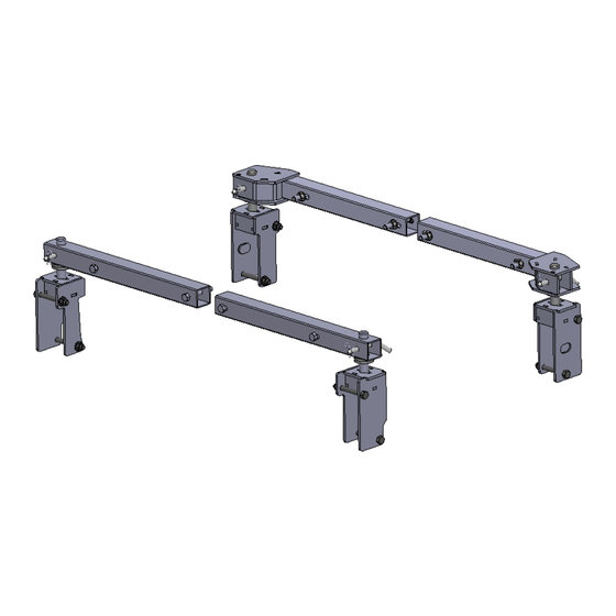
Page 4: Mounting Kit Exploded View
MOUNTING HARDWARE PARTS IDENTIFICATION pub.rh.2020.24.2_PROTO_revA... -
Page 5: Mounting Kit Parts List
PARTS LIST PARTS LIST #3124 SUPER RAIL MOUNTING KIT IITEM DESCRIPTON PART NO. QTY. 3112 FRONT BASE RAIL 31120601 BASE RAIL RELEASE PIN 08060001 **PS REAR BASE RAIL 312309 *DS REAR BASE RAIL 312308 BASE RAIL BOLT 1/2” -13 X 3 1/2” GD 5 98010187 1/2”... -
Page 6: Truck Preparation
TRUCK PREPARATION TRUCK PREPARATION 1. Check part quantities using the Parts List. 2. Block vehicle wheels. Some vehicles may require you to raise the rear of the truck in order to make it easier to drill for installing the mounting brackets on the truck frame. 3. -
Page 7: Template Method
TEMPLATE METHOD TEMPLATE METHOD 1. Lay the template in the truck bed, centering it from side-to-side, and parallel to the end of the truck bed using the dimension “X” listed in “Truck Bed Dimension Table.” 2. Mark the 4 holes as indicated below, making sure the template does not move (see Installation Tip). INSTALLATION TIP: The TEMPLATE should be orientated as shown in the drawing below. -
Page 8: Installation
INSTALLATION INSTALLATION Mounting Bracket Installation Part 1: Bracket Placement & Bed Hole Locations Since most truck beds are not installed square to the frame or are the same distance from the back of the cab, the installer will need to make sure the bed holes line up properly with the center of each mounting post hole. The basic steps in this section are as follows: •... -
Page 9: Rear Mounting Bracket Installation
INSTALLATION INSTALLATION 4. Drill the first 1/16” pilot hole through the truck bed over the rear hole on the driver side where you made the mark during the “Marking Bed for Drilling.” The bit should come down through the 1” mounting post hole, piercing the transparent tape, aiding the centering of the bracket front-to-rear and side-to-side. -
Page 10: Part 2 - Bracket Installation
INSTALLATION INSTALLATION Part 2: Drilling the Bed & Bracket Installation 1. Remove the mounting brackets and use a 2” hole saw centered over the 1/16” pilot hole and cut the bed for the mounting posts. 2. De-bur inside the holes and use a paint stick to touch up the edges. Rear Bracket Installation 1. -
Page 11: Part 3 - Final Installation Procedures
You may need to loosen the bolts on the mounting brackets below if binding occurs. Adjust as needed and retighten the bolts. 3. Reinstall the mounting posts, the mounting post flanges on front post, base rails, and the SuperGlide hitch, until the assembly can be removed freely without binding. - Page 12 MANUFACTURED BY: PULLIAM ENTERPRISES, INC. 13790 East Jefferson Blvd. Mishawaka, IN 46545 (574) 259-1520 • (800) 443-2307 info@pullrite.com • www.pullrite.com...
Need help?
Do you have a question about the SuperRail Traditional Series and is the answer not in the manual?
Questions and answers