
Related Manuals for iSMA CONTROLLI Touch Point Series


Summary of Contents for iSMA CONTROLLI Touch Point Series
- Page 1 Touch Point User Manual Hardware www.ismacontrolli.com DMP254en | 1st Issue rev. 3 | 07/2024...
-
Page 2: Table Of Contents
Table of Contents Introduction ..........................3 Revision History..........................3 Safety Rules..........................4 Technical Specification ......................5 Hardware Specification ......................7 Panel Versions..........................7 4.1.1 Touch Point Series........................7 4.1.2 Touch Point VAV Series ......................7 Dimensions [mm] ..........................9 Touch Panel ............................9 4.3.1 LEDs ............................10 4.3.2 LED Modes .......................... -
Page 3: Introduction
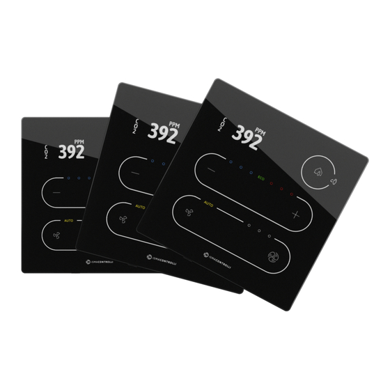
The Touch Point is a modern comfort management wall panel with two most popular open communication protocols: Modbus RTU/ASCII and BACnet MS/TP. The Touch Point is available in two lines: Touch Point series (basic) and Touch Point VAV series (no fan control). Panels are available in different configurations of sensors (temperature, CO2, and humidity), colors, and versions with or without a display (only the Touch Point series). The panel is equipped with a TFT display and touch buttons. ... -
Page 4: Safety Rules
Touch Point Hardware User Manual 2 Safety Rules • Improper wiring of the product can damage it and lead to other hazards. Make sure that the product has been correctly wired before turning the power on. • Before wiring or removing/mounting the product, make sure to turn the power off. Failure to do so might cause an electric shock. -
Page 5: Technical Specification
(applies to version with display) Backlight 3 intensity modes Buttons 5 (Touch Point series) / 3 (Touch Point VAV series) 3 blue and 3 red for temperature 3 white for fan (only the Touch Point series) 1 white for occupancy... - Page 6 Touch Point Hardware User Manual Humidity Relative From 5% to 95% RH (without condensation) Screw Connector Type Removable screw terminals Maximum cable size 1.5 mm (24…16 AWG) Housing Material Plastic, self-extinguishing ABS Mounting Standard 60 mm wall back box Dimensions Metric 86.00x86.00x14.50 mm Inches...
-
Page 7: Hardware Specification
4 Hardware Specification This section outlines all details regarding hardware specification of the Touch Point panel. 4.1 Panel Versions 4.1.1 Touch Point Series Touch Point series - basic line of the Touch Point panels: • available with or without a display, •... - Page 8 Touch Point Hardware User Manual TP-HC-DISP-B TP-HC-DISP-W Table 3. Touch Point panel models Model Panel Code Sensors Display Color Temperature Humidity Blac Touch TP-VAV-DISP-B Point TP-VAV-DISP-W ...
-
Page 9: Dimensions [Mm]
• 3 white LEDs for fan signalization (only the Touch Point series); • 1 white LED for fan auto mode signalization (only the Touch Point series). Auto-calibration Touch buttons are cyclically auto-calibrated. During the process, buttons are not responsive; in such case, wait a few seconds and press the button again. -
Page 10: Leds
2 white LEDs for signalizing occupancy status; • 3 blue and 3 red LEDs for temperature signalization (cooling or heating); • 4 white LEDs for fan modes indication (only the Touch Point series); • 1 ECO LED; • 1 navigation LED to localize the panel in the dark. -
Page 11: Power Supply
Touch Point Hardware User Manual The buzzer may be activated or deactivated using the DEVICE_CONFIGURATION register/ object (bit 0, BUZZER). Register Value Description Buzzer deactivated Buzzer activated Table 5. The BUZZER values By default, the buzzer is active. 4.5 Power Supply 4.5.1 DC Power Supply Connection Figure 7. -
Page 12: Rj45 Power Supply Connection
Touch Point Hardware User Manual 4.5.3 RJ45 Power Supply Connection Figure 9. RJ45 power supply connection 4.6 Communication The Touch Point panel supports Modbus RTU/ASCII and BACnet MS/TP communication protocols, using 2 RJ45 sockets and a screw terminal. The panel has one USB type C (USB 2.0) port for communication with the iSMA Configurator and FCU Updater software. -
Page 13: Rs485 Network Termination
Touch Point Hardware User Manual Figure 11. RS485 connection 4.6.2 RS485 Network Termination Transmission line effects often present a problem for data communication networks. These problems include reflections and signal attenuation. To eliminate the presence of reflections of signal from the end of the cable, the cable must be terminated at both ends with a resistor across the line adequate to its characteristic impedance. -
Page 14: Restoring Default Settings
Touch Point Hardware User Manual Figure 12. DIP switch location 4.7.1 Restoring Default Settings The first switch provides a possibility to restore default settings in the panel. In order to do so, follow the steps below: Figure 13. Restoring default settings •... -
Page 15: Selecting Communication Protocol
Touch Point Hardware User Manual Variable Default Value Stop bits Data bits Parity bits None Protocol Modbus RTU Modbus address Replay delay None Table 6. Default values 4.7.2 Selecting Communication Protocol The second switch selects between the available communication protocols, Modbus RTU/ ASCII or BACnet MS/TP: Figure 14. -
Page 16: Rotary Switch
Touch Point Hardware User Manual 4.8 Rotary Switch 4.8.1 Setting Device Address Figure 16. Rotary switch location The Touch Point panel is equipped with a rotary switch, which allows for setting a Modbus address in a range from 0 to 9. If the switch is set to 0, the address is read from the ADDRESS register/object (decimal address: 22). -
Page 17: Mounting And Installation
Touch Point Hardware User Manual 5 Mounting and Installation 5.1 Mounting Without a Back Box It is possible to mount the Touch Point panel without a back box in walls where a square hole of at least 51 x 51 mm can be cut directly in the wall. Then, it is required to securely install the installation screws in the wall in the position of the installation holes on the frame. - Page 18 Touch Point Hardware User Manual Figure 18. Fitting the junction box, back box, and the panel Step 3: Gently push in the bottom corners of the panel to the back box. www.ismacontrolli.com DMP254en | 1st Issue rev. 3 | 07/2024 page 18 of 19...
- Page 19 Touch Point Hardware User Manual Figure 19. Fitting down corners in the back box Step 4: Screw the panel to the back box. Turn the screw clockwise. Figure 20. Screw the panel to the back box www.ismacontrolli.com DMP254en | 1st Issue rev. 3 | 07/2024 page 19 of 19...
Need help?
Do you have a question about the Touch Point Series and is the answer not in the manual?
Questions and answers