
Related Manuals for iSMA CONTROLLI SfAR-S-8AI2DO


Summary of Contents for iSMA CONTROLLI SfAR-S-8AI2DO
- Page 1 SfAR-S-8AI2DO User Manual Expansion Module - 8 Analog Inputs, 2 Digital Outputs www.ismacontrolli.com DMP273en | 3rd Issue rev. 2 | 05/2022...
-
Page 2: Table Of Contents
SfAR-S-8AI2DO User Manual Table of Contents Introduction ..........................4 Revision History..........................4 Safety Rules..........................5 Module Features........................6 Purpose and Description of the Module ...................6 Technical Specification ........................6 Dimensions ............................7 Communication........................9 Grounding and Shielding.......................9 Network Termination........................9 Setting Module Address in RS485 Modbus Network .............9 Types of Modbus Functions....................... - Page 3 SfAR-S-8AI2DO User Manual 10.1 Registered Access......................... 21 10.2 Bit Access............................24 Configuration Software ....................... 26 www.ismacontrolli.com DMP273en | 3rd Issue rev. 2 | 05/2022 page 3 of 26...
-
Page 4: Introduction
SfAR-S-8AI2DO User Manual 1 Introduction Thank you for choosing our product. This manual will help you with proper handling and operating of the device. The information included in this manual have been prepared with utmost care by our professionals and serve as a description of the product without incurring any liability for the purposes of commercial law. -
Page 5: Safety Rules
SfAR-S-8AI2DO User Manual 2 Safety Rules • Improper wiring of the product can damage it and lead to other hazards. Make sure that the product has been correctly wired before turning the power on. • Before wiring or removing/mounting the product, make sure to turn the power off. -
Page 6: Module Features
3 Module Features 3.1 Purpose and Description of the Module The SfAR-S-8AI2DO module allows for measuring voltages and currents. Values are read via RS485 (Modbus), so the module can be easily integrated with popular PLCs, HMI, or PC equipped with the appropriate adapter. -
Page 7: Dimensions
SfAR-S-8AI2DO User Manual Current input mode Max. current ±30.72 mA 0-20 mA -20-20 mA Resolution 3.75 μA Current input mode Max. current 20 mA 4-20 mA Resolution 1 ‰ ADC processing time 16 ms/channel Isolation 1000 V DC Digital Outputs... - Page 8 SfAR-S-8AI2DO User Manual Figure 1. Dimensions www.ismacontrolli.com DMP273en | 3rd Issue rev. 2 | 05/2022 page 8 of 26...
-
Page 9: Communication
SfAR-S-8AI2DO User Manual 4 Communication 4.1 Grounding and Shielding In most cases, I/O modules will be installed in an enclosure along with other devices, which generate electromagnetic radiation. Relays, contactors, transformers, motor controllers, etc. are examples of such devices. Radiation can induce electrical noise into both power and signal lines, as well as direct radiation into the module. - Page 10 SfAR-S-8AI2DO User Manual Addr www.ismacontrolli.com DMP273en | 3rd Issue rev. 2 | 05/2022 page 10 of 26...
-
Page 11: Types Of Modbus Functions
SfAR-S-8AI2DO User Manual Addr Table 3. Setting module address in RS485 Modbus network, using DIP switch 4.4 Types of Modbus Functions There are 4 types of Modbus functions supported by the SfAR modules: Type Beginning Address Variable Access Modbus Command... -
Page 12: Configuration Registers
SfAR-S-8AI2DO User Manual • turn the switch SW6 on; • turn the power on; • when power and communication LED is lit, turn the switch SW6 off WARNING! After restoring the default configuration, all values stored in the registers will be cleared as well. -
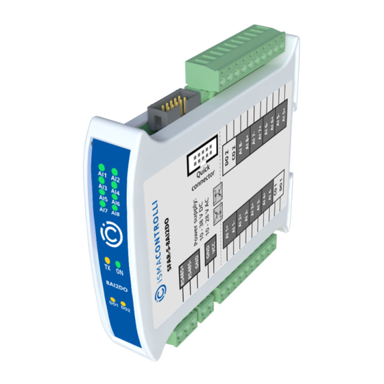
Page 13: Indicators
SfAR-S-8AI2DO User Manual 5 Indicators Figure 2. Indicators Indicator Description Power Supply The LED indicates that the module is correctly powered Communication The LED lights up when the unit received the correct packet and sends the answer Inputs State The LED indicates that the signal to input is connected... -
Page 14: Connections
SfAR-S-8AI2DO User Manual 6 Connections 6.1 Block Diagram Figure 3. Block diagram 6.2 Power Supply Connection 6.2.1 DC Power Connection Figure 4. DC power connection www.ismacontrolli.com DMP273en | 3rd Issue rev. 2 | 05/2022 page 14 of 26... -
Page 15: Ac Power Connection
SfAR-S-8AI2DO User Manual 6.2.2 AC Power Connection Figure 5. AC power connection 6.3 Communication Bus Connection Figure 6. Communication bus connection 6.4 Connection of Analog Inputs 6.4.1 Connection of Current Measurement Figure 7. Connection of current measurement www.ismacontrolli.com DMP273en | 3rd Issue rev. 2 | 05/2022... -
Page 16: Connection Of Voltage Measurement
SfAR-S-8AI2DO User Manual 6.4.2 Connection of Voltage Measurement Figure 8. Connection of voltage measurement 6.5 Connection of Digital Outputs 6.5.1 Connection of PNP Output Figure 9. Connection of PNP output 6.5.2 Connection of NPN Output Figure 10. Connection of NPN output 6.6 Quick Connector... - Page 17 SfAR-S-8AI2DO User Manual Thanks to this solution, it is enough to the power supply and RS485 communication to one of the devices in the group, and the others will be powered and communicated with ribbon cable. The Quick Connector is sufficient to connect up to 10 devices next to each other.
-
Page 18: Selecting Input Mode
SfAR-S-8AI2DO User Manual 7 Selecting Input Mode Each input can be used to measure voltage (by default) or current. To change the operating mode, it is necessary to modify software settings and the position of jumpers inside the module as shown below. -
Page 19: Analog Filtering
SfAR-S-8AI2DO User Manual 8 Analog Filtering If the measured signal is interrupted, it is possible to eliminate the disruptions by switching the lowpass filter on. It is possible to configure the filter for all inputs (it is not possible to enable the filter for only one input). The filter parameter corresponds to the filter time constant. -
Page 20: Dip Switch
SfAR-S-8AI2DO User Manual 9 DIP Switch Figure 15. DIP switch Switch Function Description Module address +1 Setting module address from 0 to 31 Module address +2 Module address +4 Module address +8 Module address +16 Restoring default settings Restoring default settings Table 8. -
Page 21: Module Registers
SfAR-S-8AI2DO User Manual 10 Module Registers 10.1 Registered Access Modbus Decimal Register Name Access Description Address Address Address 30001 0x00 Version/Type Read Version and type of the device 30002 0x01 Switches Read Switches state 40003 0x02 Baud Rate Read/write RS485 baud rate... - Page 22 SfAR-S-8AI2DO User Manual Modbus Decimal Register Name Access Description Address Address Address 30056 0x37 Analog 4 Read 30057 0x38 Analog 5 Read 30058 0x39 Analog 6 Read 30059 0x3A Analog 7 Read 30060 0x3B Analog 8 Read 30061 0x3C Value of 1. Alarm...
- Page 23 SfAR-S-8AI2DO User Manual Modbus Decimal Register Name Access Description Address Address Address 1 – remember the value of 40080 0x4F Alarm Settings 2 Read/write the alarm, until reset by the master via Modbus 40081 0x50 Alarm Settings 3 Read/write 40082...
- Page 24 SfAR-S-8AI2DO User Manual Modbus Decimal Register Name Access Description Address Address Address value from selected inputs 40096 0x5F Output 2 settings Read/write (if not select either of the two above options than is used average value of selected inputs) 40097...
- Page 25 SfAR-S-8AI2DO User Manual Modbus Dec Address Register Name Access Description Address Address 0x334 Alarm 5 Read Alarm state 5 0x335 Alarm 6 Read Alarm state 6 0x336 Alarm 7 Read Alarm state 7 0x337 Alarm 8 Read Alarm state 8...
- Page 26 SfAR-S-8AI2DO User Manual 11 Configuration Software The SfAR Configurator is a software which is designed to set the communication module registers over Modbus network as well as to read and write the current value of other registers of the module. It's a convenient way to test the system as well as to observe real-time changes in the registers.
Need help?
Do you have a question about the SfAR-S-8AI2DO and is the answer not in the manual?
Questions and answers