
Related Manuals for iSMA CONTROLLI SfAR-1M-1AI1DO


Summary of Contents for iSMA CONTROLLI SfAR-1M-1AI1DO
- Page 1 SfAR-1M-1AI1DO User Manual Expansion Module - 1 Analog Input, 1 Digital Output www.ismacontrolli.com DMP264en | 3rd Issue rev. 1 | 05/2022...
-
Page 2: Table Of Contents
SfAR-1M-1AI1DO User Manual Table of Contents Introduction ..........................3 Revision History..........................3 Safety Rules..........................4 Module Features........................5 Purpose and Description of the Module ...................5 Technical Specification ........................5 Dimensions ............................7 Communication........................8 Grounding and Shielding.......................8 Network Termination........................8 Types of Modbus Functions......................8 Communication Settings........................9... -
Page 3: Introduction
SfAR-1M-1AI1DO User Manual 1 Introduction Thank you for choosing our product. This manual will help you with proper handling and operating of the device. The information included in this manual have been prepared with utmost care by our professionals and serve as a description of the product without incurring any liability for the purposes of commercial law. -
Page 4: Safety Rules
SfAR-1M-1AI1DO User Manual 2 Safety Rules • Improper wiring of the product can damage it and lead to other hazards. Make sure that the product has been correctly wired before turning the power on. • Before wiring or removing/mounting the product, make sure to turn the power off. -
Page 5: Module Features
3 Module Features 3.1 Purpose and Description of the Module The SfAR-1M-1AI1DO module allows voltage or current measurement and has one digital output. Values are read via the RS485 (Modbus), so it can be easily integrated with popular PLCs, HMI, or PC equipped with the appropriate adapter. - Page 6 SfAR-1M-1AI1DO User Manual Inputs No. of inputs Absolute maximum input voltage ±60 V Voltage input impedance 100 k Ω Voltage measurement accuracy ±0.2% Voltage input mode Max. voltage ±16.386 V 0-10 V -10-10 V Resolution 1 mV Voltage input mode Max.
-
Page 7: Dimensions
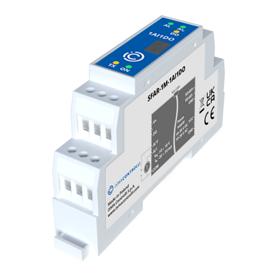
SfAR-1M-1AI1DO User Manual Interface RS485 Up to 128 devices Table 2. Technical specification 3.3 Dimensions The appearance and dimensions of the module are shown below. The module is mounted directly to the rail in the DIN industry standard. Figure 1. Dimensions www.ismacontrolli.com... -
Page 8: Communication
SfAR-1M-1AI1DO User Manual 4 Communication 4.1 Grounding and Shielding In most cases, I/O modules will be installed in an enclosure along with other devices, which generate electromagnetic radiation. Relays, contactors, transformers, motor controllers, etc. are examples of such devices. Radiation can induce electrical noise into both power and signal lines, as well as direct radiation into the module. -
Page 9: Communication Settings
SfAR-1M-1AI1DO User Manual Type Beginning Address Variable Access Modbus Command 40001 Output Registers Registered 4, 6, 16 Read/write Table 3. Types of Modbus functions supported by the module 4.4 Communication Settings The data stored in the module's memory is given in the 16-bit registers. The access to registers is via Modbus RTU or Modbus ASCII. - Page 10 SfAR-1M-1AI1DO User Manual Modbus Address Decimal Address Hex Address Name Values 40004 0x03 Stop Bits 1 – one stop bit 2 – two stop bits 40004 0x03 Data Bits 7 – 7 data bits 8 – 8 data bits 40006...
-
Page 11: Indicators
SfAR-1M-1AI1DO User Manual 5 Indicators Figure 2. Indicators Indicator Description The LED indicates that the module is correctly powered The LED lights up when the unit received the correct packet and sends the answer VIN IIN The LED indicates that the signal to input is connected and is different from The LED indicates that the output is on Table 6. -
Page 12: Connections
SfAR-1M-1AI1DO User Manual 6 Connections 6.1 Block Diagram Figure 3. Block diagram 6.2 Power Supply Connection 6.2.1 DC Power Connection Figure 4. DC power connection 6.2.2 AC Power Connection Figure 5. AC power connection www.ismacontrolli.com DMP264en | 3rd Issue rev. 1 | 05/2022... -
Page 13: Communication Bus Connection
SfAR-1M-1AI1DO User Manual 6.3 Communication Bus Connection Figure 6. Communication bus connection 6.4 Connection of Analog Inputs 6.4.1 Connection of Voltage Measurement Figure 7. Connection of voltage measurement 6.4.2 Connection of Current Measurement Figure 8. Connection of current measurement 6.5 Connection of Digital Output 6.5.1 PNP Type... -
Page 14: Npn Type
SfAR-1M-1AI1DO User Manual 6.5.2 NPN Type Figure 10. Connection of NPN type digital output www.ismacontrolli.com DMP264en | 3rd Issue rev. 1 | 05/2022 page 14 of 19... -
Page 15: Analog Filtering
SfAR-1M-1AI1DO User Manual 7 Analog Filtering If the measured signal is interrupted it is possible to eliminate the disruptions by switching the lowpass filter on. It is possible to configure the filter for all inputs (it is not possible to enable the filter for only one input). The filter parameter corresponds to the filter time constant. -
Page 16: Module Registers
SfAR-1M-1AI1DO User Manual 8 Module Registers 8.1 Registered Access Modbus Decimal Register Name Access Description Address Address Address 30001 0x00 Version/Type Read Version and type of the device 30002 0x01 Address Read Module Address 40003 0x02 Baud Rate Read/write RS485 baud rate... - Page 17 SfAR-1M-1AI1DO User Manual Modbus Decimal Register Name Access Description Address Address Address bit no 1 in the register 40052 40056 0x37 Alarm – Min Voltage Read/write Minimum value of voltage. If voltage drops below this voltage bit no 1 in the...
-
Page 18: Bit Access
SfAR-1M-1AI1DO User Manual Modbus Decimal Register Name Access Description Address Address Address 40065 0x40 Alarm Hysteresis Read/write Hysteresis for alarm Table 7. Registered access 8.2 Bit Access Modbus Dec Address Register Name Access Description Address Address 0x320 Voltage Input Read... -
Page 19: Configuration Software
SfAR-1M-1AI1DO User Manual 9 Configuration Software The SfAR Configurator is the type of software, which is designed to set the communication module registers over Modbus network as well as to read and write the current value of other registers of the module. It is a convenient way to test the system as well as to observe real-time changes in the registers.
Need help?
Do you have a question about the SfAR-1M-1AI1DO and is the answer not in the manual?
Questions and answers