
Related Manuals for Canon P1


Summary of Contents for Canon P1
- Page 1 Buffer Pass Unit-P1/P2 SERVICE MANUAL Canon February 16, 2022 Rev. 2 COPYRIGHT 2022 CANON INC. CANON Buffer Pass Unit-P1 Rev. 2 PRINTED IN U.S.A. ©...
- Page 2 When changes occur in applicable products or in the contents of this manual, Canon will release technical information as the need arises. In the event of major changes in the contents of this manual over a long or short period, Canon will issue a new edition of this manual.
- Page 3 Important Notices Explanation of Symbols The following symbols are used throughout this Service Manual. Symbols Explanation Symbols Explanation Check. Remove the claw. Check visually. Insert the claw. Check a sound. Push the part. Disconnect the connector. Connect the power cable. Connect the connector.
- Page 4 Important Notices 2. In the digital circuits, '1' is used to indicate that the voltage level of a given signal is "High", while '0' is used to indicate "Low". (The voltage value, however, differs from circuit to circuit.) In addition, the asterisk (*) as in "DRMD*" indicates that the DRMD signal goes on when '0'.
-
Page 5: Table Of Contents
Contents Contents Safety Precautions....................1 Points to Note Before Servicing......................2 Points to Note at Cleaning........................2 Notes on Assembly/Disassembly......................2 Points to Note when Tightening a Screw....................2 1. Product Overview.....................4 Specifications............................5 Specifications............................5 Name of Parts............................. 6 External View............................6 Cross Section............................6 2. - Page 6 Contents Removing the Buffer Pass Motor (M401)....................23 PCB..............................24 Removing the Buffer Pass Controller PCB (PCB401)................24 5. Adjustment..................... 25 Basic Adjustment..........................26 Basic Adjustments..........................26 APPENDICES......................27 Service Tools.............................28 Solvents and Oils..........................28 Special Tools............................28 General Circuit Diagram........................29 General Circuit Diagram........................29...
-
Page 7: Safety Precautions
Safety Precautions Points to Note Before Servicing.... 2 Points to Note at Cleaning....2 Notes on Assembly/Disassembly..2... -
Page 8: Points To Note Before Servicing
Safety Precautions Points to Note Before Servicing • At servicing, be sure to turn OFF the power source according to the specified steps and disconnect the power plug. • At the time of assembly and disassembly, be sure to place a sheet of paper under the parts to prevent them from being soiled or foreign matter from entering the parts. - Page 9 Safety Precautions The recommended torque value is shown below as a reference value. Type of Screws RS tight W Sems Binding Fastened member Metal Resin Metal Resin Metal Resin Metal Resin Tightening torque Approx. Approx. Approx. Approx. Approx. Approx. Approx. Approx.
-
Page 10: Product Overview
Product Overview Specifications........5 Name of Parts........6... -
Page 11: Specifications
1. Product Overview Specifications Specifications Item Description Remarks Placement Center Installation Built-in type Paper Type Thin Paper, Plain Paper, Heavy Paper, Recy- Transfer from the host machine (Buffer Pass Delivery Tray) cled Paper, Clear Film, Labels, Postcard Stacking Size Feed direction: 139.7 to 457.0 mm Long original paper (630mm, 1200mm) is availa- (Buffer Pass Delivery Tray) Width direction: 100.0 to 305.0 mm... -
Page 12: Name Of Parts
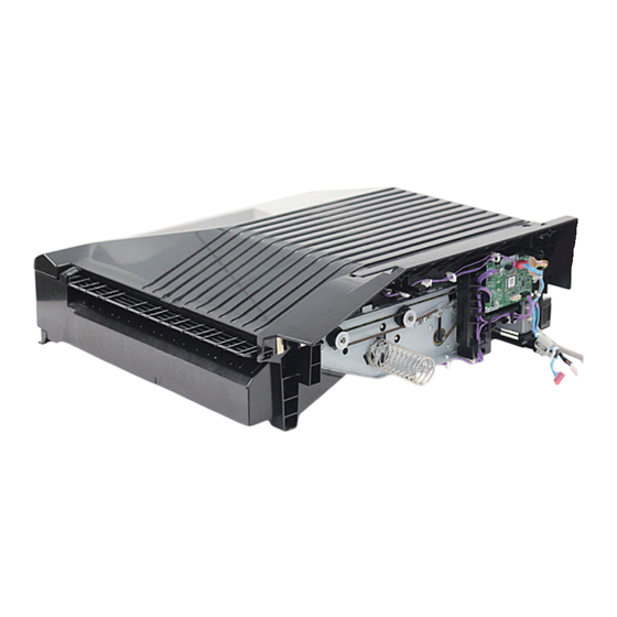
1. Product Overview Name of Parts External View Name Buffer Pass Feed Outlet Port Buffer Pass Delivery Tray Cross Section Name Feed Roller Buffer Pass Inlet Sensor Buffer Pass Exit Sensor OPEN Detection Sensor Buffer Pass Feed Outlet Port... -
Page 13: Technical Explanation
Technical Explanation Basic Configuration....... 8 Controls..........10 Basic Operation........11 Jam Detection........12 Fan Operation........13 Power Supply........14 Upgrading..........15... -
Page 14: Basic Configuration
Communication Communication Sensor Buffer Pass Motor Controller PCB Related Service Mode • (Lv.1) COPIER > DISPLAY > VERSION > BF-PASS For Buffer Pass Unit-P1 • (Lv.1) COPIER > DISPLAY > VERSION > BF-PAS2 For Buffer Pass Unit-P2 Related Error Code... - Page 15 2. Technical Explanation • E503-0041: Error in communication between the Finisher and Buffer Pass Unit • E503-0042: Error in communication between the Finisher and Buffer Pass Unit...
-
Page 16: Controls
2. Technical Explanation Controls Controls Item Reference Basic Operation “Basic Operation” on page 11 Jam Detection “Jam Detection” on page 12 Fan Operation “Fan Operation” on page 13 Power Supply “Power Supply Route” on page 14 Upgrading “Upgrading” on page 15... -
Page 17: Basic Operation
2. Technical Explanation Basic Operation Basic Operation The device feeds paper that is fed from the Staple Finisher / Booklet Finisher. Drive Configuration The following is a diagram showing the drive system of the Buffer Pass Unit. PS402 PS401 M401 Notation Name M401... -
Page 18: Jam Detection
2. Technical Explanation Jam Detection Overview The following diagram shows the arrangement of sensors used to detect jams in the Buffer Pass Unit. PS403 PS402 PS401 Jam Types Jam Code Jam type Sensor Sensor Name 100A Delay PS401 Inlet Sensor 100B Delay PS402... -
Page 19: Fan Operation
2. Technical Explanation Fan Operation The 2 fans are equipped in the Buffer Pass Unit which control temperature's rising to prevent image defect when the toner's temperature rises in the host machine. FM401 FM402 Notation Name Error Code FM401 Buffer Pass Inlet Cooling Fan E551-8021 E551-8022 FM402... -
Page 20: Power Supply
2. Technical Explanation Power Supply Power Supply Route 24V and 5V power are supplied to the Buffer Pass Controller PCB through the Finisher Controller PCB. Buffer Pass Controller PCB Finisher Controller PCB Host Machine (FU1) Motor Driver Motor (M401) Fuse (FU3) Fan (... -
Page 21: Upgrading
2. Technical Explanation Upgrading Upgrading When upgrading the firmware of the Buffer Pass Controller PCB, upgrade from the host machine. (Refer to the service manual for the host machine as to the detail.) -
Page 22: Periodical Service
Periodical Service Periodical Service Operation Item..17... -
Page 23: Periodical Service Operation Item
3. Periodical Service Periodical Service Operation Item Periodically Replaced Parts There are no parts that need to be periodically replaced on the buffer pass unit. Consumable Parts There is no consumable parts on the buffer pass unit. -
Page 24: Parts Replacement And Cleaning
Parts Replacement and Cleaning Removing this Machine from the Host Machine........... 19 List of Parts......... 22 Motor........... 23 PCB.............24... -
Page 25: Removing This Machine From The Host Machine
4. Parts Replacement and Cleaning Removing this Machine from the Host Machine Detaching from the Host Machine CAUTION: Check that the main power switch is OFF and the power plug is disconnected from the outlet. - Page 26 4. Parts Replacement and Cleaning...
- Page 27 4. Parts Replacement and Cleaning...
-
Page 28: List Of Parts
4. Parts Replacement and Cleaning List of Parts Sensors, Motor, PCB PS403 M401 PCB401 PS402 PS401 Name Main Unit Refer to PS401 Buffer Pass Inlet Sensor Product Configuration PS402 Buffer Pass Exit Sensor Product Configuration PS403 OPEN Detection Sensor Product Configuration M401 Buffer Pass Feed Motor Product Configuration... -
Page 29: Motor
4. Parts Replacement and Cleaning Motor Removing the Buffer Pass Motor (M401) ■ Procedure 1. Turn over the Buffer Pass Unit [1]. 2. Loosen the tensioner screw [2] and remove the belt [3]. 3. Remove the 2 motor screws [4]. •... -
Page 30: Pcb
4. Parts Replacement and Cleaning Removing the Buffer Pass Controller PCB (PCB401). ■ Procedure 1. Remove the Buffer Pass Controller PCB [1]. • 6 Connectors [2] • 1 Screw [3] • 1 locking support [4]... -
Page 31: Adjustment
Adjustment Basic Adjustment........ 26... -
Page 32: Basic Adjustment
5. Adjustment Basic Adjustment Basic Adjustments Buffer pass unit does not have adjustment work. -
Page 33: Appendices
APPENDICES Service Tools........28 General Circuit Diagram......29... -
Page 34: Service Tools
Service Tools Service Tools Solvents and Oils Name Uses Remarks Alcohol Cleaning; e.g., • Do not bring near fire. • Procure locally. Super Lubu Grease Worm gear part of Primary Charging Assembly • Tool No: FY9-6005 and Pretransfer Charging Assembly. Special Tools None... -
Page 35: General Circuit Diagram
General Circuit Diagram General Circuit Diagram General Circuit Diagram Buffer Pass Feed Motor OPEN Detection Sensor M401 PS403 Host Machine, Buffer Pass I/F 12 11 J81D 9 10 PCB404 Buffer Pass Controller PCB Download 14 13 12 11 J82DH J81DH J82D J81D FM402...
Need help?
Do you have a question about the P1 and is the answer not in the manual?
Questions and answers