Table of Contents
Advertisement
Quick Links
Advertisement
Table of Contents

Related Manuals for Koven Bidop 7


Summary of Contents for Koven Bidop 7
- Page 1 GTIN: 00894912002159...
-
Page 2: Table Of Contents
TABLE OF CONTENTS SECTION 1 Basic Operation Warnings & Cautions Introduction ........................1 Features ........................1 Indications for Use, Contraindications, & Applications ........2 1-1 Doppler Arterial & Venous Applications ............…2 1-2 PPG (Photoplethysmography) Arterial & Venous Applications ......2 1-3 Fetal Applications .................... - Page 3 TABLE OF CONTENTS Mode Settings for Optional Photoplethysmography (PPG) Probe 5-2-17 AC / DC / BP Mode ................26 5-2-18 COUNT ..................... 26 Mode Settings for optional 2.25 MHz probe (ST2M20S8C) 5-2-19 DISP (FHR Display Mode ..............27 5-2-20 Sound ....................27 5-2-21 Upper (Upper Limit for FHR) ............
-
Page 4: Section 1 Basic Operation
Section 1 Section 1 Basic Operation... -
Page 5: Warnings & Cautions
WARNINGS & CAUTIONS ® CAUTION Use the Bidop 7 under normal operating conditions, according to the instructions provided in this operation manual and under the operating conditions stated in the product specifications. CAUTION Federal law restricts this device to sale by or on the order of a licensed healthcare practitioner. -
Page 6: Introduction
7 has not been tested for heating or migration in the MR environment. CAUTION Perform ultrasound testing/procedures prudently using the principle of ALARA (As Low As Reasonably Achievable). Bidop and Smart-V-Link are registered trademarks of Koven Technology, Inc., St. Louis, MO... -
Page 7: Indications For Use, Contraindications, & Applications
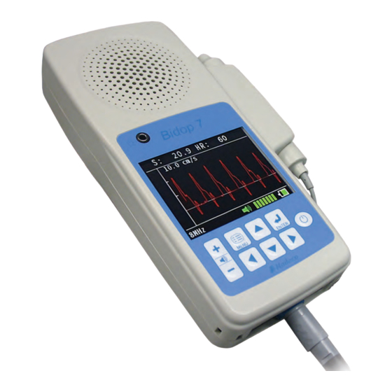
APPLICATIONS INDICATIONS FOR USE The Bidop 7 is intended for the detection of arterial and venous blood flow in the extremities as well as fetal heart sounds. The Bidop 7 displays bidirectional velocity waveforms, numerical data and fetal heart rate with heartbeat indicator. The Bidop 7 probe selection is 2, 5, 8, and 10 MHz. -
Page 8: Controls
Bidop ® CONTROLS FRONT VIEW & PROBE 1) PROBE CONNECTOR To connect the probe to the Doppler 2) HEADSET CONNECTOR To connect a headset (not provided) 3) COMMUNICATION PORT To connect the Doppler to a computer (for use with optional Smart-V-Link ®... -
Page 9: Operation Panel
Bidop ® CONTROLS OPERATION PANEL VOLUME CONTROL To adjust sound volume BUTTON : To increase volume : To decrease volume Press longer than 1 sec to mute MENU BUTTON To enter and exit the Menu UP / DOWN BUTTONS (MENU mode) To scroll through available Menu op- tions (Freeze mode) To display next memory data LEFT / RIGHT BUTTONS... -
Page 10: Setup & Operation
NOTE Be sure to push the connector into the probe connection port until it clicks into place. To disconnect the probe, hold the Bidop 7, and pull straight out on the base of the connector. Power button TURNING THE UNIT ON / OFF... -
Page 11: Checking The Battery Level
Bidop ® SETUP & OPERATION CHECKING THE BATTERY LEVEL Battery level The battery level indicator is shown in the indicator lower right corner of the screen. The battery level indicator shows the battery level in 5 stages as shown below. Full Charging Charge the battery when the battery level indicator is low. -
Page 12: Basic Operation
Bidop ® BASIC OPERATION MEASURING BLOOD VELOCITY This section explains the fundamentals ® of using the Bidop 7 to measure blood velocity. For detailed instructions on performing specific tests, please refer to Section 2 Vascular Testing Instructions. Connect the probe and press the power button to turn the unit ON. - Page 13 Bidop ® BASIC OPERATION MEASURING BLOOD VELOCITY (cont.) Place the probe on the measurement area at an angle of approximately 45° to 60° against flow and locate the point where maximum Doppler sounds are heard. CAUTION The probe transducer tip is thin and delicate. Please handle with care and use the probe cap when not in use.
-
Page 14: Ppg: Arterial Pulse Waveform Studies
Bidop ® BASIC OPERATION PPG: ARTERIAL WAVEFORM STUDIES (Requires the optional PPG probe {PG-30}, supplied separately) Arterial pulse waveform studies by photoplethysmography are performed to determine the presence or absence of pulsatile flow and to assess the state of perfusion in the tissue area immediately beneath the sensor site. -
Page 15: Measuring Fetal Heart Rate (Fhr) (Data Or Wave Mode)
Bidop ® BASIC OPERATION MEASURING FETAL HEART RATE (FHR) (DATA or WAVE mode) (Requires optional 2.25 MHz probe (ST2M20S8C), supplied separately) ® This section explains the fundamentals of using the Bidop 7 with a fetal probe to measure fetal heart rate. Connect the 2.25 MHz probe and press the power button to turn the Doppler on. - Page 16 Bidop ® BASIC OPERATION MEASURING FETAL HEART RATE (FHR) (DATA or WAVE mode) (cont.) Place the probe on the measurement area at a right angle (90°) to the skin surface, and move slowly to locate maximum Doppler heart sounds. The probe needs to just lightly touch the skin.
-
Page 17: Mhz Beep Mode
Bidop ® BASIC OPERATION 2.25 MHz BEEP MODE (Requires optional 2.25 MHz probe (ST2M20S8C), supplied separately) This section explains the fundamentals of using the Bidop ® 7 with a 2.25 MHz probe in BEEP mode to display blood velocity waveforms within a set limit. Connect the 2.25 MHz probe and press the power button to turn the Doppler on. - Page 18 Bidop ® BASIC OPERATION 2.25 MHz BEEP MODE (cont.) When testing is complete, press the probe button or enter button to FREEZE the waveform. NOTE To change the LIMIT-1 value at any time during the exam, press the up or down arrow(s).
-
Page 19: Mode & Menu Settings
Bidop ® MODE & MENU SETTINGS MENU 5-1-1 Menu Operation Various settings are available within the MENU mode. Some menu selections also have sub- menus. For details about available menu settings, see the charts in sections 5-1-2 & 5-1-3 Press the Menu button on the operation panel to display the MENU. -
Page 20: Menu For Blood Velocity Measurement Mode
Bidop ® MODE & MENU SETTINGS MENU (Cont.) 5-1-2 Menu for Blood Velocity Measurement Mode For measuring blood flow velocity Connect a 5, 8 or 10 MHz probe to select Bold face selections indicate default settings. Menu Sub Menu Selections M/F* STORE 1 to 30, FREEZE... -
Page 21: Menu For Ppg (Photoplethysmography)(Measurement & Freeze)
Bidop ® MODE & MENU SETTINGS MENU (Cont.) 5-1-3 Menu for PPG (Photoplethysmography) (Measurement & Freeze) For measuring and observing PPG waveforms Connect the PPG probe (PG-30) to select measurement Press the probe button to select freeze mode; press again to exit Bold face selections indicate default settings. -
Page 22: Menu For Fetal Heart Rate (Fhr) Mode
Bidop ® MODE & MENU SETTINGS MENU (Cont.) 5-1-4 Menu for Fetal Heart Rate (FHR) Mode (Measurement & Freeze) For measuring Fetal Heart Rate (FHR) and observing FHR waveforms Connect the 2.25 MHz fetal probe ( ) to select measurement ST2M20S8C Press the probe button to select freeze mode;... -
Page 23: Menu For 2.25 Mhz Beep Mode (Measurement & Freeze)
Bidop ® MODE & MENU SETTINGS MENU (Cont.) 5-1-5 Menu for 2.25 MHz BEEP Mode (Measurement & Freeze) For observing blood velocity waveforms; provides an audible alert when velocity exceeds a set limit Connect the 2.25 MHz probe ( ) to select measurement ST2M20S8C Press the probe button to select freeze mode;... -
Page 24: Mode Setting Details
Bidop ® MODE & MENU SETTINGS MODE SETTING DETAILS 5-2-1 MEMORY - STORE Press the Menu button to go to the MENU screen. Choose MEMORY and press the Right button or the Enter button to display the submenu. Select STORE and press Enter The first memory number available will be selected and displayed automatically to the right side of the menu... -
Page 25: Memory - Read
Bidop ® MODE & MENU SETTINGS MODE SETTING DETAILS (Cont.) 5-2-2 MEMORY – READ Press the Menu button to go to the MENU screen. Choose MEMORY and press the Right button or the Enter button to display the submenu. Use the Up or Down button to select READ and press Enter Use the Up &... -
Page 26: Mode (Waveform Mode)
Bidop ® MODE & MENU SETTINGS MODE SETTING DETAILS (Cont.) 5-2-4 MODE (Waveform Mode) Press the Menu button to go to the MENU screen. Use the Up or Down buttons to choose MODE and press the Right button or the Enter button to display the available settings. -
Page 27: Time (Time Scale)
Bidop ® MODE & MENU SETTINGS MODE SETTING DETAILS (Cont.) 5-2-6 TIME (Time Scale) Press the Menu button to go to the MENU screen. Use the Up or Down buttons to choose TIME and press the Right button or the Enter button to display the available settings. -
Page 28: Others - Freeze
Bidop ® MODE & MENU SETTINGS MODE SETTING DETAILS (Cont.) 5-2-9 OTHERS – FREEZE Press the Menu button to go to the MENU screen. Use the Up or Down buttons to choose OTHERS and press the Right button or the Enter button display the submenu. -
Page 29: Others - Smooth (Smoothing)
Bidop ® MODE & MENU SETTINGS MODE SETTING DETAILS (Cont.) 5-2-12 OTHERS – SMOOTH (Smoothing) Press the Menu button to go to the MENU screen. Use the Up or Down buttons to choose OTHERS and press the Right button or the Enter button display the submenu. -
Page 30: Others - Data1 / Data2
Bidop ® MODE & MENU SETTINGS 5-2-15 OTHERS - DATA1 / DATA2 Press the Menu button to go to the MENU screen. Use the Up or Down buttons to choose OTHERS and press the Right button or the Enter button display the submenu. -
Page 31: Ac/Dc/Bp Mode
Bidop ® MODE & MENU SETTINGS MODE SETTINGS FOR OPTIONAL PPG PROBE (PG-30) (supplied separately) 5-2-17 AC/DC/BP MODE Press the Menu button to go to the MENU screen. Use the Up or Down buttons to choose MODE and press the Right button or the Enter button to display the available... -
Page 32: Mode Settings For Optional 2.25 Mhz Probe (St2M20S8C)
Bidop ® MODE & MENU SETTINGS MODE SETTINGS FOR OPTIONAL 2.25 MHz PROBE (ST2M20S8C) (supplied separately) 5-2-19 DISP (FHR Display Mode) Press the Menu button to go to the MENU screen. Use the Up or Down buttons to choose DISP and press the Right button or the Enter button to display the available... -
Page 33: Mode Settings For 2.25 Mhz Beep Mode
Bidop ® MODE & MENU SETTINGS MODE SETTINGS FOR 2.25 MHz BEEP MODE (To select, connect the optional 2.25 MHz probe (ST2M20S8C) and set DISP to BEEP mode) 5-2-23 DISP/BEEP (Display for BEEP mode, Waveform / Numerical data) Press the Menu button to go to the MENU screen. -
Page 34: Numerical Data
Bidop ® NUMERICAL DATA To switch from waveform to numerical data on the LCD, press the Right button . To switch back to waveform, press the Left button The following numerical parameters are displayed in data mode. Definitions Parameters Abbrs. Systolic velocity [cm/s] or Systolic Doppler shift [kHz] Mean velocity [cm/s] or... -
Page 35: External Outputs
Bidop ® EXTERNAL OUTPUTS HEADSET (OPTIONAL) When a headset is used (not supplied), sound from the speaker will be cut off. COMMUNICATION PORT (USB INTERFACE) ® ® Used to connect the Bidop 7 to a computer to use with the optional Smart-V-Link software for observation of the waveform in high resolution or to create a report of standardized testing modules. -
Page 36: Maintenance
Bidop ® MAINTENANCE Perform the following performance check at least once a year. Make sure there is no damage to the unit or any of its components. Gently shake the Doppler and make sure there are no sounds of loose components inside. Turn the unit on and make sure the LCD display correctly. -
Page 37: Operating Principles
Bidop ® 10. OPERATING PRINCIPLES 7 is designed to obtain blood flow velocity through the use of ultrasound, which is Model Bidop ® transmitted from the probe to the patient’s body and reflected by the blood (hemocyte, etc.) The unit amplifies the high frequency oscillation output and then supplies it to the transmitter trans- ducer. -
Page 38: Block Diagram
Bidop ® 11. BLOCK DIAGRAM CPU Circuit Area Switch Backup Circuit Circuit Back Light Circuit RAM + ROM External Interface Circuit Switch Connector Circuit Analog Circuit Area Power Supply Circuit Area Forward/ +3.3V Probe +5.0V Reverse Isolation Pre-amplifier Battery -5.0V Circuit (NI-MH) Circuit... -
Page 39: Specifications
Bidop ® 12. SPECIFICATIONS Probes Freq. Model# GTIN# Ispta* (in situ) [mW/cm²] (For transcutaneous use): 2 MHz ST2M25S8C 00894912002814 94 mW/cm² or less 5 MHz ST5M05S8A 00894912002753 720 mW/cm² or less 8 MHz ST8M05S8A 00894912002760 720 mW/cm² or less 10 MHz ST10M5S8A 00894912002784 720 mW/cm²... -
Page 40: Operation, Storage & Transport Environments
Bidop ® 13. OPERATION, STORAGE & TRANSPORT OPERATING ENVIRONMENT • 10° to 37°C • 85% humidity or less with no condensation CAUTION Do not drop or place in an area where the unit may fall. CAUTION Care should be taken to avoid RF emitters, eg. RFID, diathermy, electrocautery, mobile phones, computers, &... -
Page 41: Cleaning
Bidop ® 15. CLEANING Clean the Doppler & probes after use. DOPPLER BOX To clean the Doppler box, wipe down with a damp cloth, then with a soft dry cloth. Take care not to allow water to penetrate the unit. CAUTION The Doppler box should not have direct contact with the patient or be placed in the sterile area. -
Page 42: Disposal Of Device
Warranty periods on probes, adaptors & accessories vary. Please refer to your purchase invoice for additional warranty terms. In the event of malfunction during the warranty period, please contact Koven Technology, Inc. at 314-542-2101 or info@koven.com. The warranty does not cover defects resulting from accidents or misuse and is void if modifications of parts are attempted without permission. -
Page 43: Safety Standards
7 should assure that it is used in such an environment. Emissions test Compliance Electromagnetic environment - guidance The Bidop 7 uses RF energy only for its internal function. RF emissions Group 1 Therefore, its RF emissions are very low and are not likely CISPR 11 to cause any interference in nearby electronic equipment. - Page 44 Bidop ® Guidance and Manufacturer’s Declarations (cont.) Electromagnetic Immunity 7 is intended for use in the electromagnetic environment specified below. The user of the ® The Bidop ® Bidop 7 should assure that it is used in such an environment. Electromagnetic environment - Immunity test IEC60601 test level...
- Page 45 To assess the electromagnetic environment due to fixed RF transmitters, an electromagnetic site survey should be considered. If the measured field strength in the location in which the Bidop 7 is used exceeds the appli- cable RF compliance level above, the Bidop 7 should be observed to verify normal operation. If abnormal perfor- mance is observed, additional measures may be necessary, such as reorienting or relocating the Bidop 7.
-
Page 46: Section 2 Vascular Testing Instructions
Section 2 Section 2 Vascular Testing Instructions... -
Page 47: Ankle Brachial Index
Bidop ® Vascular Testing Instructions 1. ANKLE BRACHIAL INDEX (ABI) The Ankle Brachial Index is the ratio of the highest systolic pressure at the arm to the systolic pressure at the ankle. This simple test is performed much like taking a standard blood pressure, except that a Doppler is used instead of stethoscope. - Page 48 Bidop ® Vascular Testing Instructions 1. ANKLE BRACHIAL INDEX (ABI) (Cont.) Record the systolic pressure at that point, then repeat on the other arm. To calculate the ABI, use the highest arm systolic pressure to rule out subclavian steal syndrome. Take the systolic pressures at the ankle Place a blood pressure cuff snugly above the ankle and connect a sphyg to the cuff.
-
Page 49: Segmental Blood Pressures
Bidop ® Vascular Testing Instructions 2. SEGMENTAL BLOOD PRESSURES Segmental pressure studies are performed with the same method as an Ankle Brachial Index, but incorporate additional cuffs wrapped above and below the knee, and optionally at the high thigh, in addition to the ankle. Significant pressure differences between adjacent cuff sites indicate narrowing of the artery or blockage in that portion of the leg. - Page 50 Bidop ® Vascular Testing Instructions 2. SEGMENTAL BLOOD PRESSURES Interpreting the Results Observe pressure differences between adjacent cuff sites on the same leg. Pressure differences between cuff sites are used to localize the disease. Pressure difference between two adjacent levels of less than 20 mmHg is considered normal within limits.
-
Page 51: Ppg Toe Pressures & Toe Brachial Index
Bidop ® Vascular Testing Instructions 3. PPG TOE PRESSURES & TOE BRACHIAL INDEX (TBI) (Requires the optional PPG probe) PPG (photoplethysmography) toe pressure studies and related TBI’s (Toe Brachial Index) are performed to assess the vascular condition of the foot by obtaining systolic pressures at the toe. - Page 52 Bidop ® Vascular Testing Instructions 3. PPG TOE PRESSURES & TOE BRACHIAL INDEX (TBI) (Cont.) Watch the LCD and wait for steady cyclic waveform motion to appear. NOTE If the waveform is not steady or absent, check the sensor for good contact, the limb for possible vasoconstriction, and the pulse for ectopic beats.
-
Page 53: Venous Reflux
Bidop ® Vascular Testing Instructions 4. VENOUS REFLUX (Requires the optional PPG probe) Venous reflux studies use a PPG probe affixed adjacent to the posterior tibial artery. The patient is asked to dorsiflex the foot, which acts as a pump for venous augmentation. - Page 54 Bidop ® Vascular Testing Instructions 4. VENOUS REFLUX (Cont.) After dorsiflexing, the patient should relax the foot and avoid all movement. The test is complete when the waveform on the LCD returns to the baseline amplitude. The Bidop ® 7 will automatically freeze and display the results.
- Page 55 Distributed by: Koven Technology, Inc. 477 N. Lindbergh Blvd., Suite 220 St. Louis, MO 63141 Tel: 800-521-8342 • Fax: 314-542-6020 E-mail: info@koven.com www.koven.com GLN: 0894912002005 Bidop 7 Operation Manual ® Copyright © Koven Technology, Inc. OM-1685 rev0...
Need help?
Do you have a question about the Bidop 7 and is the answer not in the manual?
Questions and answers