
Subscribe to Our Youtube Channel
Related Manuals for Xylem WTW WA 700/2


Summary of Contents for Xylem WTW WA 700/2
- Page 1 OPERATING MANUAL OPERATING MANUAL ba75349e03 08/2020 WA 700/2 RETRACTABLE ARMATURE (2 BAR)
- Page 2 WA 700/2 Copyright © 2020 Xylem Analytics Germany GmbH Printed in Germany.1spd ba75349 08/2020...
-
Page 3: Table Of Contents
WA 700/2 Contents WA 700/2 - Contents Overview 5 Structure and function 5 Recommended fields of application 6 Safety instructions 7 Authorized use 7 Instrument identification 8 General safety instructions 8 Commissioning 11 Scope of delivery 11 Required components 11 Installation 12 Welding the weld-in flange into place 12 Installing the ventilating stopcock/rinsing appliance... - Page 4 WA 700/2 ba75349e03 08/2020...
-
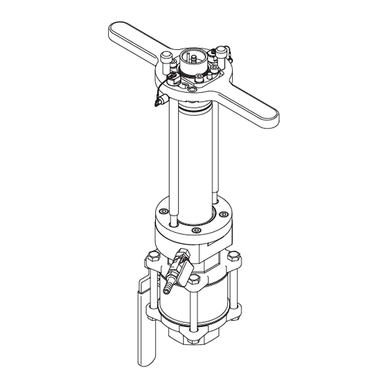
Page 5: Overview
WA 700/2 Overview Overview Structure and function Structure of the retractable armature with built-in sensor (e.g. VisoTurb 700 IQ) Bild 1-1 Overview of the retractable armature, WA 700/2 Sensor holding plate with handles Retention pin Guide bars Small ball valve (ventilating stopcock) Sensor Safety bolt Sensor adapter, specifically for the sensor type... -
Page 6: Recommended Fields Of Application
WA 700/2 Overview The WA 700/2 retractable armature is used for the installation of WTW online Features sensors in a pressure tank or pipeline. In addition, the sensor can be removed for calibration or maintenance, without having to make the container or the pipe pressureless. -
Page 7: Safety Instructions
WA 700/2 Safety instructions Safety instructions This operating manual contains essential instructions that must be followed during the commissioning, operation and maintenance of the instru- ment. Consequently, all responsible personnel must read this operating manual carefully before working with the instrument. The operating manual must always be kept available within the vicinity of the instrument. -
Page 8: Instrument Identification
WA 700/2 Safety instructions Instrument identification The name label and the maximum operational limits for pressure and tempera- ture are engraved on the sensor holding plate. The eight-digit series number and the year of manufacture appear on a label on the side of the ball valve adapter (Bild 2-1): WA 700/2 2 bar... - Page 9 WA 700/2 Safety instructions all times, that the armature only comes into contact with media that cannot corrode the materials of the armature (for details of the materials, see chapter 6 T ECHNI CAL DATA that no high external tensile or compressive loads are applied to the arma- ture, ...
- Page 10 WA 700/2 Safety instructions ba75349e03 08/2020...
-
Page 11: Commissioning
WA 700/2 Commissioning Commissioning Scope of delivery Scope of delivery of the WA 700/2: Retractable armature with short operating manual Receiving tube Retaining ring, 2-part Operating manual Maintenance agents: – Can of lubricant – Tube of joint grease Required components In addition to the retractable armature, the following components are required for the installation and fitting of a sensor:... -
Page 12: Installation
WA 700/2 Commissioning Installation 3.3.1 Welding the weld-in flange into place Warning Improper welding of the weld-in flange can lead to severe injury of personnel and damage to property. Note the following points in this regard: Only allow trained qualified personnel to carry out mounting activities. ... -
Page 13: Screwing The Retractable Armature Onto The Weld-In Flange
WA 700/2 Commissioning Attention The inlet of the rinsing appliance must be equipped with a shut-off fixture. Other- wise, measuring medium can escape into the inlet of the rinsing appliance. 3.3.3 Screwing the retractable armature onto the weld-in flange The connection between the retractable armature and weld-in flange consists of a G2"... -
Page 14: Installing The Sensor
WA 700/2 Commissioning Note The armature must be screwed on up to the stop to ensure the correct position of the sensor. If, while doing so, the lever of the large ball valve or the ventilating stopcock is unfavorably oriented (e.g. difficult to access), the housing of the large ball valve can be taken apart and remounted again with the two flanges displaced by 90 °. - Page 15 WA 700/2 Commissioning Installing the sen- Move the armature fully out: Press down against the sensor holding plate and release it by turning it counterclockwise. Then, pull the holding plate completely out. To arrest the holding plate in the final position, insert the two retention pins (pos.
- Page 16 WA 700/2 Commissioning ba75349e03 08/2020...
-
Page 17: Operation
WA 700/2 Operation Operation Bringing the sensor into the measuring position Make sure that the sensor holding plate is secured by the retention pins (especially important in the case of negative pressure in the pipe!). If necessary, discontinue the supply to the rinsing appliance. -
Page 18: Changing The Sensor
WA 700/2 Operation Changing the sensor Moving the sensor out: Bringing the Press against the sensor sensor into the holding plate and release it by changing position turning it counterclockwise. Then, pull the holding plate completely out. Arrest the holding plate in the final position using the two retention pins. - Page 19 WA 700/2 Operation Undo and remove the four screws (pos. 3) on the sensor adapter. Attention If the last screw can only be loosened with difficulty, the armature could possibly still be under pressure. In this case, check that the position of the ball valves is correct (changing position).
- Page 20 WA 700/2 Operation ba75349e03 08/2020...
-
Page 21: Maintenance And Cleaning
WA 700/2 Maintenance and cleaning Maintenance and cleaning Maintenance Maintenance The following table provides an overview of the maintenance activities. The schedule intervals are recommended values only. Depending on the condition of the armature (e.g. frequency of the sensor change), the intervals can be changed accordingly. -
Page 22: Cleaning
WA 700/2 Maintenance and cleaning Cleaning Pollution in the inside of the armature, in particular on the O-rings and on the sealing surfaces, can lead to leakages. After visual inspection, clean the inside with a brush and the following cleaning agents: Contamination Cleaning agents Reaction time at... -
Page 23: Technical Data
WA 700/2 Technical data Technical data Instrument safety Fulfills the requirements according to Article 3(3) of the Guideline 97/23/EG ("Pressure instrument guidelines"). Space required Required space for changing the sensor (sensor-dependent) Min. 80 mm Bild 6-1 Dimension drawing of the WA 700/2 Pressure difference P Min. - Page 24 WA 700/2 Technical data Connection for weld-in flange G2" internal thread Connections Rinsing connection G1/4" internal thread, closed with blank stoppers and O-ring Outlet of ventilating stopcock 8 mm hose coupling Housing components, flanges, Stainless steel 1.4571 and Materials sensor holding plate, retention high strength aluminum alloy pins AlMgCu1.5F53...
- Page 26 Beziehungen zu Kunden, bei denen wir für unsere leistungsstarke Mischung aus führenden Produktmarken und Anwendungskompetenz, unterstützt durch eine Tradition der Innovation, bekannt sind. Weitere Informationen darüber, wie Xylem Ihnen helfen kann, finden Sie auf xyleminc.com ® Service und Rücksendungen: Xylem Analytics Germany Sales GmbH &...
Need help?
Do you have a question about the WTW WA 700/2 and is the answer not in the manual?
Questions and answers