Table of Contents
Advertisement
Quick Links
Advertisement
Table of Contents

Related Manuals for TGM COT-36CNR1


Summary of Contents for TGM COT-36CNR1
- Page 1 13 SEER Condensing Unit Service Manual 2019 Version LCAC/201903...
-
Page 2: Table Of Contents
Content Part 1 General Information ..........1 2. Model Names of Outdoor Units ....................1 3. External Appearance ........................ 2 4. Features ........................... 2 Part 2 Outdoor Units ............3 1.Specifications ..........................4 2.Dimensions ..........................10 3.Typical Installation ........................ 11 4.Wiring Diagrams ........................ -
Page 3: Model Names Of Outdoor Units
2. Model Names of Outdoor Units 2.1 Outdoor Units COT-36CNR1 29×29×25 66/70 208-230V/1N/60Hz... -
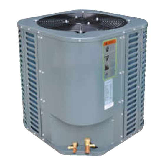
Page 4: External Appearance
COT-60CNR1 29×29×33 89/93 208-230V/1N/60Hz 3. External Appearance 3.1 Outdoor units 30k-36kBtu/h 42k-60kBtu/h 4. Features 4.1 Painted galvanized steel cabinet. 4.2 Various coil guard optional, Basic coil guard is louvered steel, it is acceptable to customize plastic or wires netting 4.3 24V low voltage control 4.4 Wide operation temperature range:Cooling range:... -
Page 5: Part 2 Outdoor Units
Part 2 Outdoor Units 1. Specifications ..............4 2. Dimensions ..............10 3. Typical Installation ............. 11 4. Wiring Diagrams ............12 5. Electric Characteristics ..........14 6. Operation Limits ............14 7. Exploded View ............. 15 8. Sound Levels ............... 24 GD Chigo Heating &... -
Page 6: Specifications
1.Specifications Cooling only type... - Page 7 R410A 60Hz Universal Outdoor Series Technical Manual Model COT-36CNR1 Outdoor power supply V/Ph/Hz 230V/1N/60HZ Capacity Btu/h 34500 Input 2930 Cooling Btu/h.W 11.70 SEER ( AHRI Certified) Btu/h.W Max. input consumption 3662.50 Max. current 16.76 Brand HITACHI Model ASH280DG-C8DU Type rotary...
- Page 8 Model COT-60CNR1 Outdoor power supply V/Ph/Hz 230V/1N/60HZ Capacity Btu/h 57000 Input 4920 Cooling Btu/h.W 11.40 SEER ( AHRI Certified) Btu/h.W Max. input consumption 6150.00 Max. current 28.15 Brand Model ABG051KAC Type scroll Capacity 14974 Compressor Input 4722 Rated current(RLA) 21.0 Locked rotor Amp(LRA) Thermal protector Refrigerant oil...
-
Page 12: Dimensions
2.Dimensions Applicable for 18-60 series... -
Page 13: Typical Installation
3.Typical Installation... -
Page 14: Wiring Diagrams
4.Wiring Diagrams Cooling only type... - Page 15 Heat pump type...
-
Page 16: Electric Characteristics
5.Electric Characteristics Outdoor Unit Model Voltage Min. Max. COT-36CNR1 208-230V 187V 244V COT-60CNR1 208-230V 187V 244V 6.Operation Limits Operation mode Outdoor temperature(℃) Room temperature(℃) Cooling operation 18~43 17~30 Heating operation -7~43 17~30 Heating Cooling Indoor temperature( ℃ WB) Indoor temperature( ℃ DB) -
Page 17: Exploded View
7. Exploded View... - Page 20 R410A 60Hz Universal Outdoor Series Technical Manual CTV13CN036A Part Name Quantity No. Part Name Quantity Cover net Electric install board weld assembly Outdoor motor Electric waterproof box Axial-flow fan Terminal board Top cover assembly Terminal board Condenser assembly Contactor Condenser Fan capacitor 5.1.1 Condenser left-side board Compressor Capacitor...
-
Page 26: Sound Levels
8.Sound Levels 12000Btu/h~24000Btu/h 48000Btu/h~60000Btu/h Outdoor Unit Microphone 1.0m Note: H= 0.5 × height of outdoor unit Note: The point A is in the middle of the whole outdoor panel. Model Noise level dB(A) COT-36CNR1 COT-60CNR1... -
Page 27: Part 3 Installation
Part 3 Installation 1. Precaution on Installation .......... 25 2. Vacuum Dry and Leakage Checking ......26 3. Additional Refrigerant Charge ........28 4. Water Drainage ............. 29 5. Insulation Work ............32 6. Test Operation .............. 34 1.Precaution on Installation 1.1. -
Page 28: Vacuum Dry And Leakage Checking
1.2. Locate The Pipe Drill a hole in the wall (suitable just for the size of the wall conduit), then set on the fittings such as the wall conduit and its cover. Bind the connecting pipe and the cables together tightly with binding tapes. Do not let air in, which will cause water leakage by condensation. - Page 29 in the pipe. At this time, it should be pumped 1 hour more. If the pump can’t achieve -755mmHg after pumping 3 hours, please check if there are some leakage points. Vacuum placement test: place 1 hour when it achieves -755mmHg, pass if the vacuum watch shows no rising.
-
Page 30: Additional Refrigerant Charge
3.Additional Refrigerant Charge Caution ● Refrigerant cannot be charged until field wiring has been completed. ● Refrigerant may only be charged after performing the leak test and the vacuum pumping. ● When charging a system, care shall be taken that its maximum permissible charge is never exceeded, in view of the danger of liquid hammer. -
Page 31: Water Drainage
4.Water Drainage 4.1 Gradient and Supporting 4.1.1 Keep the drainpipe sloping downwards at a gradient of at least 1/100. Keep the drainpipe as short as possible and eliminate the air bubble. 4.1.2 The horizontal drainpipe should be short. When the pipe is too long, a prop stand must be installed to keep the gradient of 1/100 and prevent bending. - Page 32 Ceiling cassette 4.4 Convergent drainage 4.4.1. The number of indoor units should be as small as possible to prevent the traverse main pipe overlong. 4.4.2. Indoor unit with drain pump and indoor unit without drain pump should be in different drainage system. 4.4.3.
- Page 33 ③ Stop the air conditioner running, turn off the power, and put back the cover. Stop the air conditioner. After 3 minutes, check if it has abnormity. If the collocation of drainpipes is illogical, the water will flow back overfull, which will cause the alarm lamp flashes, even overflow from the water receipt plate.
-
Page 34: Insulation Work
5.Insulation Work 5.1 Insulation material and thickness 5.1.1. Insulation material Insulation material should adopt the material which is able to endure the pipe’s temperature: no less than 70 ℃ ℃ in the high-pressure side, no less than 120 in the low -pressure side(For the cooling type machine, no requirements at the low-pressure side.) ℃... - Page 35 R410A 60Hz Universal Outdoor Series Technical Manual ② Make sure there’s no clearance in the joining pa rt of the accessorial insulation material and local preparative insulation material. 5.3 Drainage pipe insulation The connection part should be insulated, or else water will be condensing at the non-insulation part. 5.4 Note 5.4.1 The jointing area, expanding area and the flange area should be heat insulated after passing the pressure test...
-
Page 36: Test Operation
6.Test Operation The indoor unit and outdoor unit are installed properly. Tubing and wiring are correctly completed. The refrigerant pipe system is leakage-checked. The drainage is unimpeded. The ground wiring is connected correctly. The length of the tubing and the added stow capacity of the refrigerant have been recorded. ... -
Page 37: Part 4 Troubleshooting
Part 4 Troubleshooting Fault code Indoor unit fault is displayed Outdoor unit fault display... - Page 38 Parameter table for outdoor unit check and maintenance The digital tube displays the indoor unit quantity connected and communicated with during standby;The digital tube Displays the frequency value during operation of compressor; The digital tube displays “dF” during defrosting.
Need help?
Do you have a question about the COT-36CNR1 and is the answer not in the manual?
Questions and answers