Table of Contents
Advertisement
Advertisement
Table of Contents

Related Manuals for TGM CTV14CN018A

Summary of Contents for TGM CTV14CN018A
- Page 1 Technical Manual R410A 60Hz 14 SEER Top-Discharge Heat Pump Outdoor...
-
Page 2: Table Of Contents
R410A 60Hz Universal Outdoor Series Technical Manual Outdoor Unit Part 1. General Information 1. Model Names of Indoor/Outdoor Units 2. External Appearance 3. Features Part 2. Indoor Unit 1.Features 2.Dimension 3.Service Space 4.Wiring Diagrams 5. Electric Characteristics 6. The Specification of Wiring 7. -
Page 3: Part 1. General Information
14SEER AIR HANDLER SYSTEM TECHNICAL MANUAL Part 1. General Information 1. Model Names of Indoor/Outdoor Units 1.1 Indoor Units Model name Dimension(W×H×D)(inch) Power supply SEER 14 Cooling Only & Heat Pump 19-2/3×45-3/4×22 208~230V-1Ph-60Hz CTA14C018A 19-2/3×45-3/4×22 208~230V-1Ph-60Hz CTA14C024A 19-2/3×45-3/4×22 208~230V-1Ph-60Hz CTA14C030A 19-2/3×45-3/4×22 208~230V-1Ph-60Hz CTA14C036A 19-2/3×45-3/4×22 208~230V-1Ph-60Hz CTA14C042A 22×53-1/8×24-1/2 208~230V-1Ph-60Hz... -
Page 4: External Appearance
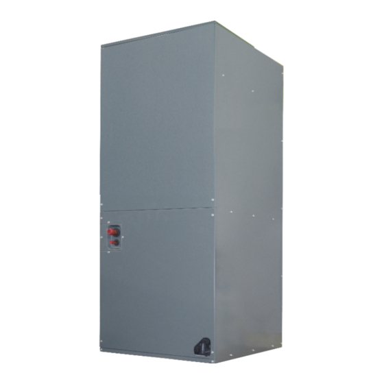
14SEER AIR HANDLER SYSTEM TECHNICAL MANUAL 2. External Appearance 2.1 Indoor unit 2.2 Outdoor unit Note: Standard outdoor unit is using plastic grill. Metal grill can be customized. -
Page 5: Features
14SEER AIR HANDLER SYSTEM TECHNICAL MANUAL 4. Features 4.1 Operation features • Long Piping & Cost Effective • Low noise operation, as low as 57dB(A) • 24V control, time delay relay, fan relay and transformer included. 4.2 Performance features • AHRI Certified & ETL listed. •... -
Page 6: Part 2. Indoor Unit
14SEER AIR HANDLER SYSTEM TECHNICAL MANUAL Part 2. Indoor Unit 1.Features 2.Dimension 3.Service Space 4.Wiring Diagrams 5.Electric Characteristics 6.The Specification of Wiring 7.Field Wiring... -
Page 7: Features
14SEER AIR HANDLER SYSTEM TECHNICAL MANUAL 1. Features (1) “A” shape coils, constructed with copper tubing and enhanced aluminum fins. (2) Direct drive motors, 3 speed, provide selections of air flow to meet desired applications. (3) φ10″large fan blade that has powerful wind speed, and the motor is covered with insulation material, which can ensure that the motor runs in a safe state. - Page 8 14SEER AIR HANDLER SYSTEM TECHNICAL MANUAL (5) Detachable air filter for cleaning or renewal Versatile 4-way convertible design for vertical up airflow, horizontal right airflow.
-
Page 9: Dimension
14SEER AIR HANDLER SYSTEM TECHNICAL MANUAL 2. Dimension... -
Page 10: Service Space
14SEER AIR HANDLER SYSTEM TECHNICAL MANUAL 3. Service Space The indoor unit should be installed in a location that meets the following requirements: INSTALLATION NOTES: . 1. When up hand discharge , how to trap or plug all drains is see the left Figure. 2. When right hand discharge , how to trap or plug all drains is see the top Figure. 3. -
Page 11: Wiring Diagrams
14SEER AIR HANDLER SYSTEM TECHNICAL MANUAL Wiring Diagrams 18K/24K/30K/36K/42K... - Page 12 14SEER AIR HANDLER SYSTEM TECHNICAL MANUAL...
-
Page 13: Electric Characteristics
14SEER AIR HANDLER SYSTEM TECHNICAL MANUAL 5. Electric Characteristics Indoor Units Indoor Fan Motor Model Voltage Min. Max. SEER 14 Cooling Only 208-230V 198V 242V 0.18 CTA14C018A 208-230V 198V 242V 0.21 CTA14C024A 208-230V 198V 242V 0.29 CTA14C030A 208-230V 198V 242V 0.40 CTA14C036A 208-230V 198V 242V 0.46 CTA14C042A 208-230V... -
Page 14: The Specification Of Wiring
14SEER AIR HANDLER SYSTEM TECHNICAL MANUAL 6. The Specification of Wiring Note: The cross-section areas of wires or lines should not be less than the corresponding ones listed in the table below;Besides, if the power wires is quite long from the unit, please choose the windings with larger cross-section area to guarantee the normal power supply. Thermostat communication wiress Indoor power Outdoor power... -
Page 15: Field Wiring
14SEER AIR HANDLER SYSTEM TECHNICAL MANUAL 7. Field Wiring 1. To avoid the electrical shock, please connect the air conditioner with the ground lug. The main power plug in the air conditioner has been joined with the ground wiring, please don't change it freely. 2. The power socket is used as the air conditioner specially. 3. -
Page 16: Part 3 Outdoor Unit
14SEER AIR HANDLER SYSTEM TECHNICAL MANUAL Part 3 Outdoor Unit 1. Dimensions 2. Service Space 3. Wiring Diagrams 4. Electric Characteristics 5. Operation Limits 6. Sound Levels 7. Refrigerate diagram... -
Page 17: Dimension
14SEER AIR HANDLER SYSTEM TECHNICAL MANUAL 1. Dimension... -
Page 18: Service Space
14SEER AIR HANDLER SYSTEM TECHNICAL MANUAL 2. Service Space... -
Page 19: Wiring Diagrams
14SEER AIR HANDLER SYSTEM TECHNICAL MANUAL 3. Wiring Diagrams SEER 14 Cooling only... -
Page 20: Electric Characteristics
14SEER AIR HANDLER SYSTEM TECHNICAL MANUAL 4. Electric Characteristics Outdoor Unit Model Outdoor Voltage Min. Max. motor (kw) 0.15 208~230V 198V 242V CTV14CN018A 0.18 CTV14CN024A 208~230V 198V 242V 0.21 CTV14CN030A 208~230V 198V 242V 0.21 CTV14CN036A 208~230V 198V 242V 0.21 CTV14CN042A 208~230V 198V 242V 0.51 CTV14CN046A... -
Page 21: Operation Limits
14SEER AIR HANDLER SYSTEM TECHNICAL MANUAL 5. Operation Limits Operation mode Outdoor temperature(℃) Room temperature(℃) Cooling operation 18~43 17~30... -
Page 22: Sound Levels
14SEER AIR HANDLER SYSTEM TECHNICAL MANUAL 6. Sound Levels Model Noise level dB(A) CTA14C018A CTA14C024A CTA14C030A CTA14C036A CTA14C042A CTA14C046A CTA14C060A Note: Sound level is measured at a point 1 m in front of the unit, at a height of (Unit body height +1)/2 m. -
Page 23: Refrigerate Diagram
14SEER AIR HANDLER SYSTEM TECHNICAL MANUAL 7. Refrigerate diagram Applicable for 18K,24K,30K,36K cooling only type Applicable for 42K,48K, 60K cooling only type... -
Page 24: Part 4 Installation
14SEER AIR HANDLER SYSTEM TECHNICAL MANUAL Part 4 Installation 1 .Precaution on Installation 2. Vacuum Dry and Leakage Checking 3. Additional Refrigerant Charge 4. Insulation Work 5. Test Operation... -
Page 25: Precaution On Installation
14SEER AIR HANDLER SYSTEM TECHNICAL MANUAL 1. Precaution on Installation 1.1. Measure the necessary length of the connecting pipe, and make it by the following way. Connect the indoor unit at first, then the outdoor unit. Bend the tubing in proper way. Do not harm them. CAUTIONS: ●... -
Page 26: Vacuum Dry And Leakage Checking
14SEER AIR HANDLER SYSTEM TECHNICAL MANUAL 2. Vacuum Dry and Leakage Checking 2.1 Vacuum Dry: use vacuum pump to change the moisture (liquid) into steam (gas) in the pipe and discharge it out of the pipe to make the pipe dry. Under one atmospheric pressure, the boiling point of water(steam temperature) is 100℃. - Page 27 14SEER AIR HANDLER SYSTEM TECHNICAL MANUAL ②. Special vacuum dry procedure ● This vacuum dry method is used in the following conditions: ● There’s moisture when flushing the refrigerant pipe. ● Rainwater may enter into the pipe. ● Vacuum dry for the first time ······ 2h pumping ③.
-
Page 28: Additional Refrigerant Charge
14SEER AIR HANDLER SYSTEM TECHNICAL MANUAL 3. Additional Refrigerant Charge Caution ● Refrigerant cannot be charged until field wiring has been completed. ● Refrigerant may only be charged after performing the leak test and the vacuum pumping. ● When charging a system, care shall be taken that its maximum permissible charge is never exceeded, in view of the danger of liquid hammer. -
Page 29: Insulation Work
14SEER AIR HANDLER SYSTEM TECHNICAL MANUAL 4. Insulation Work Insulation material and thickness 4.1.1. Insulation material Insulation material should adopt the material which is able to endure the pipe’s temperature: no less than 70℃ in the high-pressure side, no less than 120℃ in the low-pressure side(For the cooling type machine, no requirements at the low-pressure side.) Example: Heat pump type----Heat-resistant Polyethylene foam (withstand above 120℃) ◆... - Page 30 R410A 60Hz 14 SEER Universal Outdoor Series Technical Manual For construction convenience, before laying pipes, use insulation material to insulate the pipes to be deal with, at the same time, at two ends of the pipe, remain some length not to be insulated, in order to be welded and check the leakage after laying the pipes.
-
Page 31: Test Operation
14SEER AIR HANDLER SYSTEM TECHNICAL MANUAL 5.Test Operation (1) The test operation must be carried out after the entire installation has been completed. (2) Please confirm the following points before the test operation. ● The indoor unit and outdoor unit are installed properly. ● Tubing and wiring are correctly completed. ●... -
Page 32: Part 5 Unit Maintenance
14SEER AIR HANDLER SYSTEM TECHNICAL MANUAL Part 5 Unit maintenance 1 Fault indicator of indoor unit 2. Fault indicator of outdoor unit 3. Flow chart of troubleshooting 4. Exploded views and part list... -
Page 33: Fault Indicator Of Indoor Unit
14SEER AIR HANDLER SYSTEM TECHNICAL MANUAL 1. Fault indicator of indoor unit The meaning of the fault indicator: Status description Display mode No system alarm and error, normal standby Green light always on Evaporator tube temperature sensor( T 2 ) failure Red light always on Green light always on, yellow light flashing Evaporator high and low temperature protection Green light flashing... -
Page 34: Fault Indicator Of Outdoor Unit
14SEER AIR HANDLER SYSTEM TECHNICAL MANUAL 2. Fault indicator of outdoor unit The meaning of the fault indicator:... -
Page 35: Flow Chart Of Troubleshooting
14SEER AIR HANDLER SYSTEM TECHNICAL MANUAL 3. Flow chart of troubleshooting 3.1 Evaporator temperature sensor fault 3.2 Evaporator high temperature protection(For heating mode) - Page 36 14SEER AIR HANDLER SYSTEM TECHNICAL MANUAL 3.3 Evaporator low temperature protection (For cooling mode) 3.4 T3 Condenser Temperature sensor fault...
- Page 37 14SEER AIR HANDLER SYSTEM TECHNICAL MANUAL 3.5 T5 discharge temperature sensor fault 3.6 Low pressure alarm...
- Page 38 14SEER AIR HANDLER SYSTEM TECHNICAL MANUAL 3.7 High pressure alarm 3.8 T3 High temperature protection...
- Page 39 14SEER AIR HANDLER SYSTEM TECHNICAL MANUAL 3.9 High exhaust temperature protection...
-
Page 40: Exploded Views And Part List
14SEER AIR HANDLER SYSTEM TECHNICAL MANUAL 4. Exploded views and part list Air Handler Indoor unit Part Name Quantity Part Name Quantity Filter Cover plate Water pan supporter assembly Water pan components Supporter Water pan# 1 Right Volute Wind Wheel Water pan# 2 Indoor Motor Water pan fixed block Fan Motor Fixing plate assembly Water pan brace... - Page 41 14SEER AIR HANDLER SYSTEM TECHNICAL MANUAL Evaporator Water Baffle #3 Transformer Evaporator Fixing Plate #1 Upper side plate assembly 3.10 Evaporator Fixing Plate #2 Pipe Cover plate assembly 3.11 Evaporator Junction Plate Lower side plate assembly Chassis assembly Top discharge outdoor unit Quantit Part Name Part Name...
- Page 42 14SEER AIR HANDLER SYSTEM TECHNICAL MANUAL Low pressure valve welding 5.3.1.1 S.TL-ZL-FTF-A02 components Rear side-panel 14.1 Block valve body Support board 14.2 Pressure switch Right side panel Left side panel...
Need help?
Do you have a question about the CTV14CN018A and is the answer not in the manual?
Questions and answers