Page 1
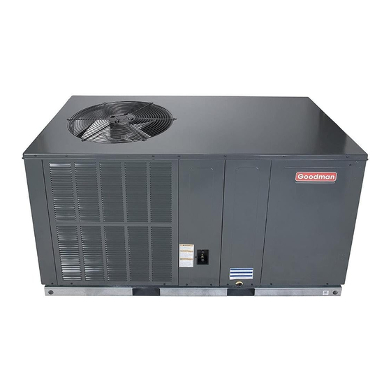
GPH13 PACKAGE HEAT PUMPS GPC13 PACKAGE COOLING HORIZONTAL MODELS WITH R-22 This manual is to be used by qualified, professionally trained HVAC technicians only. Goodman does RS6300009r4 not assume any responsibility for property damage or personal injury due to improper service March 2009 procedures or services performed by an unqualified person.
To locate an authorized servicer, please consult your telephone book or the dealer from whom you purchased this product. For further assistance, please contact: CONSUMER INFORMATION LINE ® GOODMAN BRAND PRODUCTS TOLL FREE 1-877-254-4729 (U.S. only) email us at: customerservice@goodmanmfg.com fax us at: (713) 856-1821 (Not a technical assistance line for dealers.)
Page 5
IMPORTANT INFORMATION SAFE REFRIGERANT HANDLING While these items will not cover every conceivable situation, they should serve as a useful guide. WARNING WARNING O AVOID POSSIBLE EXPLOSION: EFRIGERANTS ARE HEAVIER THAN AIR. HEY CAN "PUSH OUT" THE • EVER APPLY FLAME OR STEAM TO A REFRIGERANT CYLINDER. F YOU OXYGEN IN YOUR LUNGS OR IN ANY ENCLOSED SPACE.
PRODUCT DESIGN LOCATION & CLEARANCES NOTE: To ensure proper condensate drainage, unit must be in- stalled in a level position. In installations where the unit is installed above ground level and not serviceable from the ground (Example: Roof Top installations) the installer must provide a service platform for the service person with rails or guards in accordance with local codes or ordinances.
PRODUCT DESIGN The outdoor fan motor and the indoor blower motor are single • Compliant scroll compressors perform "quiet" shutdowns phase capacitor type motors. that allow the compressor to restart immediately without the need for a time delay. This compressor will restart even Air for condensing (cooling) is drawn through the outdoor coil if the system has not equalized.
PRODUCT DESIGN The best protection for the wiring is the smallest fuse or breaker which will hold the equipment on line during normal operation WARNING without nuisance trips. Such a device will provide maximum circuit protection. WARNING DO NOT EXCEED THE MAXIMUM OVERCURRENT DEVICE SIZE SHOWN ON THE UNIT DATA PLATE.
SYSTEM OPERATION SYSTEM OPERATION GPC/GPH13[24-60]H21* COOLING If the room thermostat fan selector switch should be set to the "on" position then the indoor blower would run continu- The refrigerant used in the system is R-22. It is clear, color- ous rather than cycling with the compressor. less, non-toxic, non-irritating, and non-explosive liquid.
SYSTEM OPERATION GPC/GPH13[24-60]H21* GPC 5 ton units: (A and AA Revision Models) GPC 2 thru 4 ton units: (A Revision Models) With the thermostat set to the heat position and a call for With the thermostat set to the emergency heat position and heat, R to W will be energized.
SYSTEM OPERATION GPC/GPH13[24-60]H21* If the thermostat is not calling for heat or cool, and the fan switch on the thermostat is returned to the automatic posi- TEST tion, the fan will stop after a 65 second delay on 2 thru 4 ton JUMPER WIRE units, and after the programmed 60 second off delay on 5 ton units with the GE X13...
Page 20
SYSTEM OPERATION Typical Package Cooling Indoor Outdoor Coil Coil Chatleff Orifice Assy Restrictor Orifice Assembly in Cooling Operation In the cooling mode the orifice is pushed into its seat forcing refrigerant to flow through the metered hole in the center of the orifice.
Page 21
SYSTEM OPERATION Typical Heat Pump System in Cooling Reversing Valve (Energized) Indoor Outdoor Coil Coil Accumulator Typical Heat Pump System in Heating Reversing Valve (De-Energized) Indoor Outdoor Coil Coil Accumulator...
SCHEDULED MAINTENANCE The owner should be made aware of the fact, that, as with any 6. Check the contacts of the compressor contactor. If they mechanical equipment the Package Cooling and Heat Pump are burned or pitted, replace the contactor. units require regularly scheduled maintenance to preserve high 7.
SERVICING SERVICING COOLING /HEAT PUMP- SERVICE ANALYSIS GUIDE Sys te m Unsatis factory Com plaint No Cooling Ope rating Cooling/He ating Pre s s ure s POSSIBLE CAUSE Test Method DOTS IN ANALYSIS Remedy GUIDE INDICATE "POSSIBLE CAUSE" • Pow er Failure Test V oltage •...
SERVICING Three phase units require a balanced 3 phase power supply to S-1 CHECKING VOLTAGE operate. If the percentage of voltage imbalance exceeds 3% the unit must not be operated until the voltage condition is corrected. WARNING Max. Voltage Deviation % Voltage = From Average Voltage X 100...
SERVICING S-2 CHECKING WIRING 5. No voltage, indicates the trouble is in the thermostat or wiring. 6. Check the continuity of the thermostat and wiring. Repair or replace as necessary. WARNING S-3B COOLING ANTICIPATOR The cooling anticipator is a small heater (resistor) in the ther- mostat.
SERVICING S-4 CHECKING TRANSFORMER AND S-8 CHECKING CONTACTOR CONTACTS CONTROL CIRCUIT A step-down transformer (208/240 volt primary to 24 volt sec- WARNING ondary) is provided with each package unit. This allows ample capacity for use with resistance heaters. DISCONNECT POWER SUPPLY BEFORE SERVICING. WARNING SINGLE PHASE 1.
SERVICING 5. Using a VOM, check for line voltage from the purple wire at the transformer (terminal 3 on 240 volt units, terminal 2 on 208 volt units) to the COM terminal on the EBTDR. Should read line voltage. If not as above, replace EBTDR. VOLT/OHM 2 Thru 4 Ton Units (AB Revision) METER...
SERVICING 5 Ton Units (A and AA Revision) S-15 CHECKING CAPACITOR NOTE: The 5 Ton AB revision models do not have a relay. CAPACITOR, RUN A run capacitor is wired across the auxiliary and main wind- On the A and AA revision 5 ton units with the GE X13 motor, ings of a single phase permanent split capacitor motor.
SERVICING Capacitance (MFD) = 2650 X Amperage S-15A RESISTANCE CHECK Voltage WARNING Volt / Ohm Meter 15 AMP FUSE AMMETER 1. Discharge capacitor and remove wire leads. TESTING CAPACITANCE WARNING S-16 CHECKING MOTORS DISCHARGE CAPACITOR THROUGH A 20 TO 30 OHM S-16A CHECKING FAN AND BLOWER MOTOR RESISTOR BEFORE HANDLING.
SERVICING 2. Using a voltmeter, check for 24 volts from terminal C to This discharge can be ignited external to the compressor if the either terminal 1, 2, 3, 4 or 5, depending on which tap is terminal cover is not properly in place and if the discharge being used, at the motor.
SERVICING 3. If a ground is indicated, then carefully remove the compres- sor terminal protective cover and inspect for loose leads or insulation breaks in the lead wires. 4. If no visual problems indicated, carefully remove the leads at the compressor terminals. OHMMETER Carefully retest for ground, directly between compressor COMP...
SERVICING NOTE: Remove jumper across defrost thermostat before re- turning system to service. WARNING S-25 TESTING DEFROST THERMOSTAT DISCONNECT POWER SUPPLY BEFORE SERVICING. 1. Install a thermocouple type temperature test lead on the tube adjacent to the defrost control. Insulate the lead point 1.
SERVICING 1. Disassemble and remove the heating element(s). S-101 LEAK TESTING 2. Visually inspect the heater assembly for any breaks in the Refrigerant leaks are best detected with a halide or electronic wire or broken insulators. leak detector. 3. Using an ohmmeter, test the element for continuity - no However, on outdoor installed systems, provisions must be reading indicates the element is open.
SERVICING 6. Continue to evacuate to a minimum of 250 microns. Close valve to vacuum pump and watch rate of rise. If vacuum WARNING does not rise above 1500 microns in three to five minutes, system can be considered properly evacuated. SCROLL COMPRESSORS 7.
SERVICING S-104 CHECKING COMPRESSOR For charging in the warmer months, 10°F superheat at the compressor is required at conditions: 95°F outdoor ambient EFFICIENCY (dry bulb temperature), 80°F dry bulb / 67°F wet bulb indoor The reason for compressor inefficiency is broken or damaged ambient, approximately 50 % humidity.
SERVICING S-109 CHECKING SUBCOOLING Temp. Gauge Pressure Temp. Gauge Pressure °F. (PSIG) Freon-22 °F. (PSIG) Freon-22 Refrigerant liquid is considered subcooled whenever its tem- 0.61 102.5 perature is lower than the saturation temperature correspond- 1.42 106.3 ing to its pressure. The degree of subcooling equals the de- 2.27 110.2 grees of temperature decrease below the saturation tempera-...
SERVICING S-111 FIXED ORIFICE RESTRICTION S-113 REFRIGERANT OVERCHARGE DEVICES An overcharge of refrigerant is normally indicated by exces- sively high head pressure and/or liquid return to the compres- The fixed orifice restriction device (flowrator) used in conjunc- sor. tion with the indoor coil is a predetermined bore (I.D.). Evaporator coils with a fixed orifice metering device could It is designed to control the rate of liquid refrigerant flow into an allow refrigerant to return to the compressor under extreme...
SERVICING S-122 REVERSING VALVE REPLACEMENT Remove the refrigerant charge from the system. CAUTION When brazing a reversing valve into the system, it is of ex- DO NOT ALLOW THE SLUDGE OR OIL TO CONTACT treme importance that the temperature of the valve does not THE SKIN, SEVERE BURNS MAY RESULT.
SERVICING S-201 CHECKING TEMPERATURE RISE S-200 CHECKING EXTERNAL STATIC PRESSURE Temperature rise is related to the BTUH output of the unit and the amount of air (CFM) circulated over the indoor coil. The minimum and maximum allowable duct static pressure is found in the Technical Information Manual.
WIRING DIAGRAMS PACKAGE SYSTEM WIRING DIAGRAM - 1 STAGE ELECTRIC HEAT TYPICAL HP ROOM THERMOSTAT SEE NOTE 1 #18 GAUGE 7 WIRE PACKAGE UNIT REQUIRED FOR LOW VOLTAGE HEAT PUMPS JUNCTION BOX YELLOW GREEN ORANGE WHITE BLUE OUTDOOR THERMOSTAT CLOSE ON TEMPERATURE FALL PACKAGE SYSTEM WIRING DIAGRAM - 2 STAGE ELECTRIC HEAT ABOVE 10 KW TYPICAL HP...
WIRING DIAGRAMS GPC/GPH13**H21* PCE* ECONOMIZER FOR GPC/GPH13**H21* Wiring is subject to change. Always refer to the wiring diagram on the unit for the most up-to-date wiring.
Need help?
Do you have a question about the GPH13 H 1 Series and is the answer not in the manual?
Questions and answers