Table of Contents
Advertisement
Quick Links
Advertisement
Table of Contents

Related Manuals for Green Power GPG5000W


Summary of Contents for Green Power GPG5000W
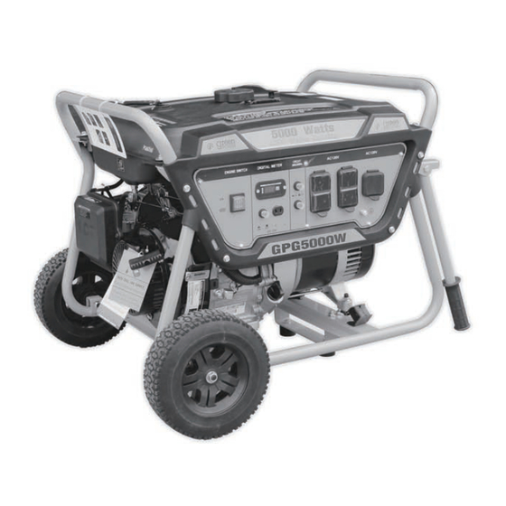
- Page 1 GPG5000W GPG5000EW...
- Page 2 Products Service Green-Power America LLC thanks you for choosing a Green-Power America product. egister your product within 10 days of purchase to ensure that you receive service. egistering your product 1. You have a record of the product purchase, 2. Customer Service can Be serve you on Warranty related issues, You can register your product in one ways as follow...
- Page 3 5000W Generator Topi c Page n i l Battery Assembly and Installation Operation Inspection,Cleaning, Maintenance and Storage Speci fications t s i GREEN-POWER AMERICA,LLC(HEREINAFTER IN SHORT “GREEN-POWER” OR “GPA” )...
- Page 4 Green-Power Green-Power Green-Power Green-Power please call specified toll free number. Service purchaser should contact Green-Power directly,send email:service@green-poweramerica.com...
- Page 5 5000W Generator Green-Power Green -Power...
-
Page 6: Safety Guidelines - Definitions
Owner’s Manual Safety Guidelines - Definitions This manual contains important information that you need to know and understand in order to protect YOUR SAFETY and to PREVENT EQUIPMENT PROBLEMS. The following symbols help you recognize this information. Please read the manual and pay attention to these sections. Save These Important Safety Instructions! Read and understand all of these safety instructions. -
Page 7: General Precautions
5000W Generator General Precautions WARNING! FAILURE TO FOLLOW THESE INSTRUCTIONS CAN RESULT IN SEVERE INJURY OR DEATH. CAUTION: FAILURE TO FOLLOW THESE INSTRUCTIONS CAN ALSO RESULT IN DAMAGE TO THE TOOL AND/OR THE ITEM YOU ARE WORKING DANGER CARBON MONOXIDE Using a generator indoors WILL KILL YOU IN MINUTES. -
Page 8: Hot Components
Owner’s Manual General Precautions (cont’d) Gasoline and Oil (cont ’d) • F uel or oil spills must be cleaned up immediately. Dispose of fluids and cleaning materials as per any local, state, or federal codes and regulations. Store oily rags in a covered metal container. •... -
Page 9: Work Area
5000W Generator General Precautions (cont’d) Work Area • Keep your work area clean and well lit. Cluttered benches and dark areas invite accidents. • Do not operate power tools in explosive atmospheres, such as in the presence of flammable liquids, gases, or dust. Generators create sparks which may ignite the dust or fumes. •... - Page 10 Owner’s Manual General Precautions (cont’d) Electrical Safety (cont’d) • All connections and conduits from the generator to the load must only be installed by trained and licensed electricians, and in compliance with all relevant local, state, and federal electrical codes and standards, and other regulations where applicable. •...
- Page 11 5000W Generator General Precautions (cont’d) Personal Safety (cont’d) • Avoid accidental starting. Make sure the power switch is in its “OFF” position, and disconnect the spark plug wire when not in use. • Remove adjusting keys or wrenches before turning the generator on. A wrench or a key that is left attached to a rotating part of the generator may result in personal injury.
-
Page 12: Heart Pacemakers
Owner’s Manual General Precautions (cont’d) Servicing Maintain labels and name plates on the generator and engine. These carry important information. If unreadable or missing, contact our service center toll free immediately for a replacement. Generator service must be performed only qualified repair personnel. Service or maintenance performed by unqualified personnel could result in a risk of injury. - Page 13 5000W Generator General Precautions (cont’d) Installation (cont’d) • If the generator is installed outdoors, it must be weatherproofed and should be soundproofed. It should not be run outdoors without protection to the generator and wiring conduit. • The generator might weigh over 100 lbs Two or more people should assist when moving or lifting this product.
- Page 14 Owner’s Manual General Precautions (cont’d) Mechanical (cont’d) • Do not operate the generator with safety guards removed. While the generator is running, do not attempt to reach around the safety guard for maintenance or any other reason. • Keep hands, arms, long hair, loose clothing, and jewelry away from moving parts. Be aware that when engine parts are moving fast they cannot be seen clearly.
- Page 15 5000W Generator General Precautions (cont’d) Extension Cord If an extension cord (not included) is used, make sure to use only UL approved cords having the correct gauge and length according to the following table: Nameplate Amps (@ full load) Cord Lengths 0 ft.- 50 ft.
-
Page 17: Assembly And Installation
5000W Generator Assembly and Installation Unpacking 1. Remove the generator and loose parts box from the carton. 2. Compare the Hardware Kit included with the inventory list below. Loose Parts (Wheel kit and handle) Check all loose parts against the following list. Contact your dealer toll free at 888.834.4218 if any of the loose parts shown are not included with your generator Hardware Check: Your Hardware Kit should include:... -
Page 18: Installation
Owner’s Manual Installation NOTE: PRIOR TO POWERING TOOLS AND EQUIPMENT MAKE SURE THE GENERATOR’S RATED VOLTAGE, WATTAGE AND AMPERAGE CAPACITY IS ADEQUATE TO SUPPLY ALL ELECTRICAL LOADS THAT THE UNIT WILL POWER. IF POWERING EXCEEDS THE GENERATOR’S CAPACITY, IT MAY BE NECESSARY TO GROUP ONE OR MORE OF THE TOOLS AND/OR EQUIPMENT FOR CONNECTION TO A SEPARATE GENERATOR. - Page 19 5000W Generator Installation (cont’d) Supporting and Mounting Mount the generator on a concrete slab capable of supporting the weight of the generator. The slab must extend on all sides beyond the frame by at least one foot. Contact a cement contractor for slab specifications if necessary.
-
Page 20: Operation
Owner’s Manual Operation NOTE: THE PARTS LISTED ABOVE ARE HELPFUL FOR LOCATING THE CONTROLS MENTIONED BELOW. Before Starting the Generator CAUTION: PRIOR TO FIRST USING THE GENERATOR, THE ENGINE MUST BE FILLED WITH HIGH QUALITY SAE 10W-30 GRADE ENGINE OIL. TO DO SO, UNSCREW AND REMOVE THE ENGINE’S OIL DIPSTICK LOCATED AT THE BOTTOM OF THE ENGINE CRANKCASE. - Page 21 5000W Generator Operation (cont’d) Starting 1. Turn the engine switch to the ON position. The engine switch enables and disables the ignition system. OFF: To stop the engine ON: To run the engine 2. The fuel valve is located under the fuel tank . When the valve lever is in the ON position, fuel is allowed to flow from the fuel tank to the carburetor.
-
Page 22: Stopping Engine
Owner’s Manual Operation (cont’d) Starting Starter Grip Starter Grip 4. Operate the Recoil Starter: Pull the starter grip lightly until you feel resistance, then pull briskly. Return the starter grip gently. Pulling the starter grip operates the recoil starter to crank the engine Operate the Electric start: Push and hold the engine switch on the “START”... - Page 23 5000W Generator Operation (cont’d) Powering 120/240 Volt AC Tools And Equipment: 1. Prior to powering tools and equipment, make sure the generator’s rated voltage, and amperage capacity is adequate to supply all electrical loads that the unit will power. If powering exceeds the generator’s capacity, it may be necessary to group one or more of the tools and/or equipment for connection to a separate generator.
- Page 24 Owner’s Manual Operation (cont’d) Powering 12 Volt DC tools and Equipment: 1. Prior to powering tools and equipment, make sure the generator’s rated voltage, and amperage capacity (12V DC) is adequate to supply all electrical loads that the unit will power. If powering exceeds the generator’s capacity, it may be necessary to group one or more of the tools and/or equipment for connection to a separate generator.
-
Page 25: Inspection, Cleaning, And Maintenance
5000W Generator Inspection, Cleaning, and Maintenance WARNING! ALWAYS MAKE SURE THE ENGINE POWER SWITCH IS IN ITS “OFF” POSITION. DISCONNECT THE SPARK PLUG WIRE FROM THE ENGINE. AND ALLOW SUFFICIENT TIME FOR THE ENGINE AND GENERATOR TO COMPLETELY COOL BEFORE PERFORMING ANY INSPECTIONS, MAINTENANCE, OR CLEANING. -
Page 26: Fuel Sediment Cup Cleaning
5000W Generator Fuel Sediment Cup Cleaning The sediment cup prevents dirt or water which may be in the fuel tank from entering the carburetor. If the engine has not been run for a long time, the sediment cup should be cleaned. 1. - Page 27 Owner’s Manual Maintenance Guide Periodic maintenance and adjustment is necessary to keep the generator in good operating condition. WARNING! Exhaust gas contains poisonous carbon monoxide. Shut off the engine before performing any maintenance. If the engine must be run, make sure the areas is well ventilated. •...
-
Page 28: Air Cleaner Maintenance
5000W Generator Air cleaner Maintenance A dirty air cleaner will restrict air flow to the carburetor. lower generator output power and deteriorate the engine emission To prevent carburetor malfunction, service the air cleaner regularly. Service more frequently when operating the generator in extremely dusty areas. WARNING! Using gasoline or flammable solvent to clean the filter element can cause a fire or explosion. - Page 29 Owner’s Manual...
- Page 30 5000W Generator Transporting/Storage...
- Page 31 Owner’s Manual GPG5000W Wiring Diagram...
- Page 32 Owner’s Manual GPG5000EW Wiring Diagram...
-
Page 33: Specifications
Owner’s M anual Specifications AC electr ical Current Output 120V @ 33.3A 60Hz Running Watts 4000W 5000W Starting Watts Four-120V 20A NEMA 5-20R Receptacle Outlet One-120V 30A NEMA L5-30R Receptacle DC electrical Outlet 12V@8.3A Gasoline engine Type 4-cycle OHV air-cool ed recoil start Displacement 1.15 Oil c apacity... - Page 34 5000W Generator A,Cylinder head system assy. Description GPA Part No. HEAD COVER COMP. BOLT GPG5000W-A-01-JD JF240.1.1-4 JF240.1.1-6 GPG5000W-A-02-JD HEAD COVER WASHER COMP JF240.1.1-5 GPG5000W-A-03-JD WASHER COVER PACKING U20.1.3-1 GPG5000W-A-04-JD HEAD COVER COMP JF240.1.1-3 GPG5000W-A-05-JD HEAD COVER PACKING JF340.2-4 GPG5000W-A-06-JD FLANGE BOLT...
- Page 35 5000W Generator B,Cylinder barrel GPA Part No. Description GB/T5787 GPG5000W-B-01-JD M6*16-8.8-Zn.D U20.14 GPG5000W-B-02-JD OIL LEVEL SWITCH ASSY GPG5000W-B-03-JD O-RING (14mm) JF340.14.1-1 GB/T6177 GPG5000W-B-04-JD GPG5000W-B-05-JD 306cc.2.1-1B CRANK CASE GPG5000W-B-06-JD BALL BEARING (6206) 20.2-6206 GPG5000W-07-JD JF168.11.2-8 WASHER( ø8.3×ø17×1) JF168.11.2-2 GPG5000W-B-08-JD LOCK PIN (10 mm) 306cc.11.2-1...
- Page 36 5000W Generator C,Crankcase cover system assy. Description GPA Part No. GPG5000W -C-01- JD DUCT COVER JF340.12-2 GB/T5787 GPG5000W -C-02- JD M8*35-8.8-Zn.D JF240.15-3B -C-03- JD OIL SCALE GPG5000W GPG5000W -C-04- JD JF340.15-5 OIL SCALE SEAL RING 20.1-35*52*7 -C-05- JD OIL SEAL...
- Page 37 5000W Generator D,Crankshaft system assy. GPA Part No. Descript io n 270cc.4.2C1 GPG5000W -D-01-JD CRANKSHAFT COMP.(Tapper shaft) GPG5000W -D-02-JD 306cc.5-1 BALANCER WEIGHT GPG5000W -D-03-JD JF420.4.2-1 CRANKSHAFT COMP.(Key shaft) GPG5000W -D-04-JD JF340.4-2 BALANCER SHAFT ASSEMBLY...
- Page 38 5000W Generator E,Piston & Connecting Rod Assy. GPA Part No. Descript io n GPG5000W -E-01-JD 306cc.3-1 COMPRESSION RING A 306cc.3-2 GPG5000W -E-02-JD COMPRESSION RING B JF340.3-3A GPG5000W -E-03-JD OIL RING A JF340.3-3B GPG5000W -E-04-JD OIL RING B JF168.3-6 GPG5000W -E-05-JD PISTON PIN CLIP (20 mm) 306cc.3-5B...
- Page 39 5000W Generator F,Air Supply System GPA Part No. Descript io n U20.1.2-17 GPG5000W-F-01-JD PIVOT ADJUSTING NUT U20.1.2-8 GPG5000W-F-02-JD ROCKER ARM PIVOT U20.1.2-9 GPG5000W-F-03-JD ROCKER ARM U20.1.2-7 GPG5000W-F-04-JD PIVOT BOLT (M8) 270cc.1.2-16 GPG5000W-F-05-JD PUSH ROD GUIDE PLATE 270CC.1.2-14 GPG5000W-F-06-JD ROD PUSH U20.1.2-15...
- Page 40 5000W Generator G,Recoil Starter Assy. GPA Part No. Descript io n GPG5000W-G-01-JD RECOIL STARTER ASSY. 270CC.13.1.1 GPG5000W-G-02-JD SETTING SCREW JF340.13.1-7 JF340.13.1-6 GPG5000W-G-03-JD SPRING RETAINER U14.13.1-8 GPG5000W-G-04-JD PLATEN SPRING JF340.13.1-5 GPG5000W-G-05-JD STARTER DETENT GPG5000W-G-06-JD DETENT SPRING JF340.13.1-4 JF240.13.1-3 GPG5000W-G-07-JD RECOIL STARTER REEL...
- Page 41 5000W Generator H, Fan Cover Assy. GPA Part No. Descript io n GPG5000W-H-01-JD SHROUD 270cc.6-1 GB/T5787 GPG5000W-H-02-JD M6*12-8.8-Zn.D JF240.13.2 GPG5000W-H-03-JD FAN COVER COMP.
- Page 42 5000W Generator I,Carburetor Assy. Description GPA Part No. GPG5000W -I-01-JD CARBURETOR ASSY. JF420.9.1C GPG5000W -I-02-JD CARBURETOR PAPER GASKET JF340.9-3 GPG5000W -I-03-JD JF340.9-1A CARBURETOR INSULATING PLATE -I-04-JD GPG5000W JF340.1-3 INTAKE PIPE GASKET...
- Page 43 5000W Generator J,Flywheel Assy. GPA Part No. Descript io n GPG5000W -J-01-JD JF240.4.1-1 FLYWHEEL JF168.4.2-2 GPG5000W -J-02-JD SPECIAL WOODRUFF KEY JF240.12-1 GPG5000W -J-03-JD COOLING FAN 270CC.13-1 GPG5000W -J-04-JD STARTER PULLEY GPG5000W -J-05-JD FLYWHEEL NUT (M16) JF240.4-1...
- Page 44 5000W Generator K,Ignition System Assy. GPA Part No. Descript io n GPG5000W-K-01-JD 128CC.10.2-1 NOISE SUPPERSSOR CAP ASSY GPG5000W-K-02-JD IGNITION COIL ASSY JF340.10.2 306cc.10.3 GPG5000W-K-03-JD STOP SWITCH CORD JF340.10-3 GPG5000W-K-04-JD STOP SWITCH CORD HOLDER GPG5000W-K-05-JD M6*25-8.8-Zn.D GB/T5787 -K-06-JD CORD GROMMENT JF340.10.2-4...
- Page 45 5000W Generator L,Starter motor System assy. GPA Part No. Descript io n GPG5000EW JF420.18-1 -L-01-JD STARTER MOTOR GPG5000EW -L-02-JD JF420.18-2 SOLENOID GPG5000EW -L-03-JD GB/T5787 M6*35-8.8-Zn.D...
- Page 46 500 0 0W Generator M,Control Assy. GPA Part No. Descript io n GPG5000W -M-01-JD CONTROL ASSY. 270CC.11.4 270CC.11.4-1 GPG5000W -M-02-JD CONTROL BASE COMP. JF340.11.3-3 GPG5000W -M-03-JD CONTROL ADJUSTING SPRING GB/T5787 GPG5000W -M-04-JD M6*35-8.8-Zn.D GB/T5787 GPG5000W -M-05-JD M6*12-8.8-Zn.D GPG5000W -M-06-JD GOVERNOR SPRING JF340.11.2-6...
- Page 47 5000W Generator S,Generator GPA Part No. JF340.25-3-1 GPG5000W -S-01-JD STATOR COVER GPG5000W JF340.25-2-2 -S-02-JD STATOR ASSY. JF340.12-1-2 GPG5000W -S-03-JD COOLING FAN GPG5000W JF168.25-4 -S-04-JD BRUSH ASSY. GPG5000W -S-05-JD GB/T5787 M5*12-8.8-Zn.D GPG5000W -S-06-JD JF340.22-1 GENERATOR STAY GPG5000W -S-07-JD GB/T6177 GPG5000W -S-08-JD GB/T5787 M6*146-8.8-Zn.D...
- Page 48 5000W Generator N,Air Cleaner GPA Parts No. JD Parts No. Description GPG5000W AIR CLEANER COVER COMP 306cc.2-1 GPG5000W -N-02 AIR CLEANER ELEMENT 306cc.2-2 GPG5000W -N-03 306cc.2-3 AIR CLEANER SEAL 306cc.2-4 GPG5000W -N-04 BREATHER GASKET 306cc.2-5 GPG5000W -N-05 AIR CLEANER CASE COMP...
- Page 49 5000W Generator O, Muffler System Assy. GPA Parts No. Factory Parts No. Descript io n GPG5000W -O-01 JD5000.7.2.1 FLER STAY COMP. EXHAUST GASKET GPG5000W -O-02 JD5000.7.2.2 GPG5000W -O-03 GB/T6177 GPG5000W -O-04 GB/T93...
- Page 50 5000W Generator P, Fuel tank system assy. GPA Parts No. Descript io n JD Parts No -P-01 GPG5000W FUEL FILLER CAP COMP JD5000.1.5-1.2 -P-02 JD5000.1.5-1.1 GPG5000W FUEL FILTER -P-03 GPG5000W JD5000.1.5-1C FUEL TANK COMP. JD5000.1.5-1.3 -P-04 OVERFLOW VALVE GPG5000W -P-05 JD5000.8-1...
- Page 51 5000W Generator Q,Control panel assy. Description GPA Parts No. JD Parts No. JD5000.21.3-1 GPG5000W-Q-01 ENGINE SWITCH ASSY. JD5000.21.3-2 GPG5000W- Q-02 DIGITAL METER JD5000.21.2 GPG5000W -Q-03 TROL PANEL COMP EARTH TERMINAL JD5000.21.3-3 GPG5000W-Q-04 5-20R GPG5000W-Q-05 120V 20A NEMA 5-20R Receptacle L5-30R...
- Page 52 5000W Generator R,Frame Comp Assy. GPA Parts No. JD Parts No. Description JD5000.17-1 GPG5000W-R-01 Frame comp JD5000.21-1 Control panel back box GPG5000W-R-02...
- Page 53 5000W Generator S,Generator GPA Part No. JF340.25-3-1 GPG5000W-S-01-JD STATOR COVER GPG5000W-S-02-JD JF340.25-2-2 STATOR ASSY. JF340.12-1-2 GPG5000W-S-03-JD COOLING FAN GPG5000W-S-04-JD JF168.25-4 BRUSH ASSY. GPG5000W-S-05-JD 20.7-M5*12 TAPPING SCREW GPG5000W-S-06-JD JF340.22-1 GENERATOR STAY GPG5000W-S-07-JD 20.5-M5 NUT (5mm) GPG5000W-S-08-JD 22-3-M6*179 FLANGE BOLT (M6X146) GPG5000W-S-09-JD JF340.18-5...
- Page 54 5000W Generator T,Wheel & Hand Assy. 10 11 Description GPA Parts No. JD Parts No. QTY. GPG5000W-T-01 20.6-M10 LOCKNUT(M10) GPG5000W-T-02 GB/T6177.1 WHEEL GPG5000W-T-03 JD5000.17.10.1-1 SHAFT GPG5000W-T-04 JD5000.17-9-4 GPG5000W-T-05 GB/T6177.1 GPG5000W-T-06 JD5000.17.10.1-2 HANDLE GPG5000W-T-07 GB/T5787 M8*40-8.8-Zn.D GPG5000W-T-08 JD5000.17-6 RUBBER GPG5000W-T-09 GB/T6177.1 GPG5000W-T-10 JD5000.17-5...
Need help?
Do you have a question about the GPG5000W and is the answer not in the manual?
Questions and answers