
Related Manuals for Green Power AgriQuip GP33TR/S


Summary of Contents for Green Power AgriQuip GP33TR/S
- Page 1 PTO DRIVEN GENERATOR SET Models: GP33TR/S – GP115TR/SF INSTRUCTION & MAINTENANCE HANDBOOK After-Sales Support – Phone: 06 759 8402 or Email: support@agriquip.co.nz...
- Page 2 Manufactured by: ITALY...
-
Page 3: Table Of Contents
Contents 1. INTRODUCTION TO THE MANUAL ...................... 5 2. DESCRIPTION OF THE GENERATING SET ..................... 6 2.1 IDENTIFICATION OF THE GENERATING SET .................. 6 2.2 GENERAL FEATURES ........................6 2.3 TECHNICAL FEATURES ........................7 2.4 ALTERNATOR ..........................7 2.5 ELECTRIC CONTROL PANEL ......................7 2.6 GEARBOX ............................ - Page 4 6.3.1. STAR CONNECTION ......................14 6.3.2. PHASES CYCLICAL DIRECTION ..................... 14 7. INSTALLATION INSTRUCTION ......................15 7.1. GENERAL INSTALLATION CRITERIA .................... 15 7.2 SAFE DISTANCE ........................... 15 7.3 INSTALLATION ..........................15 8. ELECTRICAL CONNECTIONS ....................... 16 8.1. INSTRUCTIONS FOR ELECTRICAL CONNECTIONS ............... 16 8.2.
-
Page 5: Introduction To The Manual
1. INTRODUCTION TO THE MANUAL Thank you for having chosen a AgriQuip generating set manufactured by Green Power Systems SRL in Italy. We advise you to read carefully this manual, observing safety standards for proper use and maintenance of the generating set. -
Page 6: Description Of The Generating Set
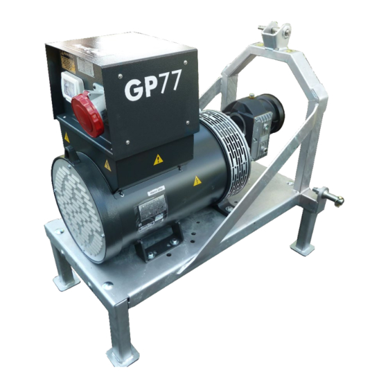
2. DESCRIPTION OF THE GENERATING SET 2.1 IDENTIFICATION OF THE GENERATING SET Please look at Fig.1. Machine type Machine code Serial number Year of manufacturing Weight Continuous power Power factor Declared frequency Rated voltage 10. Rated current 11. Performance class Fig. -
Page 7: Technical Features
2.3 TECHNICAL FEATURES 1500 RPM EQUIPMENT SPECIFICATION MODEL (ISO8528/1) 50 Hz GP33 TR/S GP55 TR/S GP77 TR/S GP95 TR/SF GP115 TR/SF 30 kVA 50 kVA 75 kVA 87.5 kVA 100 kVA Prime power at power factor 0.8 Prime power at power factor 0.8 24 kW 40 kW 60 kW... -
Page 8: Gearbox
Before carrying out any maintenance operations block the generator. We recommend performing any maintenance employing all PPE required. Every modifications made on the electrical links and/or the electrical instruments even the substitutions must be made only after our technicians approval. Unauthorized operations will also result in immediate forfeiture of the warranty. -
Page 9: Danger Zones
3.1 DANGER ZONES Following the analysis of risks during designing phase, the following table briefly shows the danger zones on a unit : Possibility Existing Severity of Exposure Danger Zone Probability Preventative measures Notes danger the danger frequency avoidance Shielding the part via appropriate Cut or permanent protection. -
Page 10: Residual Risks
DANGER OF AMPUTATION DANGER OF AMPUTATION BY BY REMOVING REMOVING PROTECTIVE PROTECTIVE PARTS: PARTS: ROTATING PARTS ROTATING PARTS Fig.1 Alternator fan and coupling area Fig.4 Gearbox DANGER OF ELECTROCUTION WHEN PROTECTION REMOVED: LIVE PARTS Fig.2 Voltage regulator open 3.2 RESIDUAL RISKS Residual risk Where to find the symbols Symbols / rules... -
Page 11: Moving The Generating Set
4. MOVING THE GENERATING SET All AgriQuip generator sets are equipped with lifting points to be used when loading and unloading the unit. Each unit’s information tag reports kilos and its mass. When moving/lifting a genset it is imperative to be extremely careful. All moving operations must be carried out be qualified people. -
Page 12: Generator Set Use Conditions
5. GENERATOR SET USE CONDITIONS AgriQuip generators are mainly used when autonomous production of electric energy is needed, or for emergency/stand-by use when the Mains fails. 5.1. WORKSPACE AND OPERATOR’S SPACE WORKSPACE 5.1.1 The working spaces of the machine are designed in function to the size of the body of the European population standardised by EN547-3 with 95% percentile. -
Page 13: Genset Uses Not Permitted
5.3. GENSET USES NOT PERMITTED It is not allowed to use AgriQuip generating sets showing any mechanical and/or electrical incompatibility between the user system and genset. The compatibility between the genset and environmental conditions must also be checked, keeping in mind that the standard unit is not projected for, installations in certain environments, ex. -
Page 14: Inductive Load
6.1.4. INDUCTIVE LOAD (electric engines in general, electric fans, motor pumps, winches, etc.) Electric engines, especially those with cage rotor, have a very high current value during start-up (up to 10 times the rated current 2) combined to a low power factor. Generally alternators mounted on our gensets are able to supply an output current equal to 2,5 times rated current for max 10- 15 sec, this period is usually sufficient to start cage engines, with a transient voltage droop of 35% (that decreases within 0.15- 0.30 sec at 15%). -
Page 15: Installation Instruction
Genset has been selected according to needs of the electrical load and to environmental conditions (temperature, altitude and humidity) Electrical equipment and panel, if not provided with generating set, are according to Green power Systems srl. • indications, to European standards in force, and to genset specifications;... -
Page 16: Electrical Connections
8. ELECTRICAL CONNECTIONS 8.1. INSTRUCTIONS FOR ELECTRICAL CONNECTIONS Wrong electrical connections can cause damage to the genset and to systems related to it. A qualified electrician should carry out electrical connections according to the standards in force, and after ensuring that the genset and User system are compatible. BEFORE CARRYING OUT THE CONNECTION, CAREFULLY READ THE LOAD APPLICATION CHAPTER OF THIS MANUAL. -
Page 17: Start-Up Instructions
9. START-UP INSTRUCTIONS 9.1. GENERAL INDICATIONS FOR START-UP All AgriQuip gensets are tested before leaving the factory. For start-up of an AgriQuip genset, few but careful operations are required, these are described in detail in this manual as well as the alternator and other equipment manuals. All start-up, maintenance, repair and modifying operations must be carried out according to safety standards and only by qualified and trained personnel. -
Page 18: Generator Starting
9.3 GENERATOR STARTING Follow the steps below to start the generator: On the front panel of the generator, set the main circuit breaker to the OFF or OPEN position. Plug in the desired electrical loads. Start the tractor engine and engage the power takeoff (PTO) drive. Increase the tractor engine RPM slowly until the voltmeter on the generator panel indicates the right value (395-415 volts and 50 hertz) Set the generator main circuit breaker to the ON or CLOSED position. -
Page 19: Ordinary Maintenance
(verbal authorisation is valid only if given directly by Green power head office). The manufacturer will null and void the warranty if the products are repaired without authorisation, even if the breakdown can clearly be attributed to a manufacturer’s defect. In any case USE ONLY ORIGINAL PARTS. -
Page 20: Warranty Terms
13. WARRANTY TERMS All Agriquip gen sets are covered with a comprehensive 12 month warranty against faulty materials and workmanship provided that: The gen set is operated in normal use as set out in the parts and operating manual; (ii) The gen set is correctly serviced and maintained as specified in this operating manual;... - Page 21 WARRANTY REGISTRATION PTO Generator Set Thank you for choosing a quality AgriQuip product! Please complete this form and simply take a photo and send to support@agriquip.co.nz or fill out the online warranty registration form on our website. Scan the QR code on the right to go directly to the form. YOUR DETAILS (The Owner) Name: _________________________________ Trading Name...
-
Page 22: Electrical Schematics
14. ELECTRICAL SCHEMATICS PTO Powered Generator Sets – 400V Three Phase Description 1) Magnetothermic 2) Alternator 3) Voltmeter 4) Three phase socket (3P+N+E) 5) Single phase socket (2P+E) - Page 23 Imported & distributed by: AgriQuip Limited 30 Hurlstone Drive, New Plymouth New Zealand 4312 Freephone: 0800 759 840 Phone: +64 6 759 8402 support@agriquip.co.nz www.agriquip.co.nz...
- Page 24 PTO GENERATOR ~ START UP & SHUT DOWN PROCEDURE ~ PTO Connection Connect the PTO shaft to the tractor PTO drive system and to the generator’s gearbox shaft. The shaft must be fully engaged with the tractor and the generator shaft. The generator and tractor shafts must be parallel as much as possible.
Need help?
Do you have a question about the AgriQuip GP33TR/S and is the answer not in the manual?
Questions and answers