
Related Manuals for ACT ACT-VCC Series


Summary of Contents for ACT ACT-VCC Series
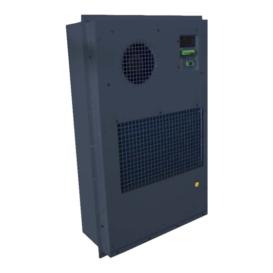
- Page 1 ACT-VCC Cabinet Air Conditioners User Manual for all models IDEAL APPLICATIONS Read this manual carefully before installation and use. www.1-act.com/enclosure-cooling...
-
Page 2: Table Of Contents
Rev A ACT-VCC Cabinet Air Conditioners User Manual Summary This manual describes the ACT-VCC Series Air Conditioners and includes the product description, working principles, wiring diagrams, operating instructions, routine maintenance, troubleshooting, and technical specifications of the models: VCC-1000-DC and VCC-3000-DC and VCC-2000-AC and... -
Page 3: Instructions
Be sure to read this manual carefully before installing or operating the unit. • To be covered by ACT’s warranty and access normal warranty service, the user(s) must comply with all local and industry standards, as well as with the instructions in this User Manual. -
Page 4: Product Dimensions
Rev A ACT-VCC Cabinet Air Conditioners User Manual Product Dimensions Figure 2.1 Product dimensions for ACT-VCC-1000-DC Figure 2.2 Product dimensions for ACT-VCC-3000-DC... -
Page 5: Application Notes
Rev A ACT-VCC Cabinet Air Conditioners User Manual Figure 2.3 Product dimensions for ACT-VCC-2000-AC Figure 2.4 Product dimensions for ACT-VCC-5000-AC 2.1 Application Notes DC models are intended for use in industrial equipment applications that utilize a 48V DC power supply, while AC models are intended for use in industrial equipment applications that utilize a 230V AC power supply. -
Page 6: Working Principles
Rev A ACT-VCC Cabinet Air Conditioners User Manual Safety and Use Instructions: Transport the unit in an upright position Do not store in a high temperature, high humidity environment (<70℃, <95%). If the unit will not be in use for a long period, disconnect the main supply power 2.2 Working Principles... -
Page 7: Technical Specifications
Rev A ACT-VCC Cabinet Air Conditioners User Manual Technical Specifications Note: Parameters will be subject to the latest specification Table 2.1 Technical Specifications for ACT-VCC-1000-DC 25°C 35°C 45°C 25°C 35°C 45°C 55°C 55°C 77°F 95°F 113°F 131°F 77°F 95°F 113°F 131°F... -
Page 8: Air Circulation And Remote Mounting
Rev A ACT-VCC Cabinet Air Conditioners User Manual Table 2.3 Technical Specifications for ACT-VCC-2000-AC 3500 3500 35°C/ 95°F 60Hz 35°C/ 95°F 60Hz 25°C / 75°F 60Hz 25°C / 75°F 60Hz 3000 3000 35°C / 95°F 50Hz 35°C / 95°F 50Hz 25°C / 75°F... -
Page 9: Operation Of The Unit
Rev A ACT-VCC Cabinet Air Conditioners User Manual Figure 2.5: Cabinet air circulation Ducting Gasket 2.5 Operation of the Unit When the unit is turned on, it will perform a self-test before starting standard operation. If any faults are detected during the self-test, the system goes into the ‘fault’... -
Page 10: Condensate Handling
The Air Conditioner should be packaged in a wooden crate, as in figure 4.1 with foam protection surrounding the unit. 1 pcs/ box or 10 pcs / pallet for ACT-VCC-1000-DC 1 pcs/ box or 6 pcs / pallet for ACT-VCC-3000-DC or ACT-VCC-2000-AC 1 pcs/ box or 3 pcs / pallet for ACT-VCC-5000-AC •... -
Page 11: Unpacking And Acceptance
Rev A ACT-VCC Cabinet Air Conditioners User Manual 4. Unpacking and Acceptance • Make sure the package is upright as shown in Figure 4.1 before you open the package, Figure 4.1 packaging • Please check that the packing straps are unbroken and that the wooden box is undamaged, not deformed or wet. - Page 12 ACT-VCC Cabinet Air Conditioners User Manual Figure 5.2 Dimensions for cut-out in enclosure door for the ACT-VCC-1000-DC Figure 5.3 Dimensions for cut-out in enclosure door for the ACT-VCC-3000-DC Figure 5.4 Dimensions for cut-out in enclosure door for the ACT-VCC-2000-AC 30.23”/ 768mm...
-
Page 13: Electrical Connection
Rev A ACT-VCC Cabinet Air Conditioners User Manual Figure 5.5 Dimensions for cut-out in enclosure door for the ACT-VCC-5000-AC Installation steps: 1. Mark the cabinet with the cut-out dimensions according to Figure 5.2 – 5.5 depending on model 2. Cut out the shaded area 3. - Page 14 Rev A ACT-VCC Cabinet Air Conditioners User Manual Table 5.1: Wiring Requirements for DC Models MODEL ACT-VCC-1000-DC ACT-VCC-3000-DC Power supply - 48 VDC* - 48 VDC* (GND/RTN: positive, -48: negative) (GND/RTN: positive, -48: negative) Power supply range -42 VDC ~ - 60 VDC.
- Page 15 Rev A ACT-VCC Cabinet Air Conditioners User Manual Figure 5.6 System wiring diagram for the ACT-VCC-1000-DC Intfan Extfan RS485 -48V CTRL T/R- T/R+...
- Page 16 Rev A ACT-VCC Cabinet Air Conditioners User Manual Figure 5.7 System wiring diagram for the ACT-VCC-3000-DC -48V In tfa n Extf a n R S 4 8 5 CTRL T/R- T/R+...
- Page 17 Rev A ACT-VCC Cabinet Air Conditioners User Manual Figure 5.8 System wiring diagram for the ACT-VCC-2000-AC Evap. Temp. Sensor Cond. Temp. Sensor INT. Temp. Sensor CTRL T/R- T/R+ 4μF 2.5μF Lighting Arrester...
- Page 18 Rev A ACT-VCC Cabinet Air Conditioners User Manual Figure 5.9 System wiring diagram for the ACT-VCC-5000-AC...
-
Page 19: Running And Testing
Rev A ACT-VCC Cabinet Air Conditioners User Manual 6. Running and Testing 6.1 Pre-operational checks After Air Conditioner is installed and the electrical connection is completed, please complete the following checklist: Table 6.1 Pre-operational checks Steps Checking items Ensure all screws are torqued to appropriate values Ensure that there is enough space around the internal and external air ducts of the air conditioner. -
Page 20: Led Display Parameter Setting Guide
Rev A ACT-VCC Cabinet Air Conditioners User Manual Table 6.2 Definition of the symbols Indicator Icon Definition Is lit Is blinking Parameter setting Under setting status Self-test status *Heating status *Heater is running *Heater has failed when Cooling Compressor is running... -
Page 21: Maintenance And Warranty
175 DC FAN Internal Fan 31.002 175 DC FAN External Fan 41.013 MDYT V22 Main Control Board Table 7.3 Spare parts list for the ACT-VCC-3000-DC Spare part PN Spare part name Spare part model Quantity 31.001 225DC FAN Internal/external fan 41.011... - Page 22 Rev A ACT-VCC Cabinet Air Conditioners User Manual Table 7.4 Spare parts list for the ACT-VCC-2000 AC Spare part PN Spare part name Spare part model Quantity 31.051 190 AC FAN Internal Fan 31.052 225 AC FAN External Fan 41.019...
- Page 23 Rev A ACT-VCC Cabinet Air Conditioners User Manual Alarm code and Processing method During normal operation, the LED displays the return air temperature leaving the air conditioner. An alarm signal will alert the user to an error and the alarm code error message will be displayed alternately with the return air temperature.
-
Page 24: Service And Repair
Contact ACT Other system faults 7.2 Service and Repair Disclaimer The warranty is limited to the delivered product(s) and ACT is not responsible for any loss that may be derived by equipment failure. - Page 25 Rev A ACT-VCC Cabinet Air Conditioners User Manual Warranty period: 1-year limited warranty Warranty Section from ACT’s PURCHASE ORDER TERMS AND CONDITIONS • Buyer’s Property. All drawings, tools, fixtures, materials and other items supplied or paid for by Buyer shall be and remain the property of Buyer. All such items shall be used only in the performance of work under this Order unless Buyer consents otherwise in writing.
Need help?
Do you have a question about the ACT-VCC Series and is the answer not in the manual?
Questions and answers