
Related Manuals for ACT ACT-VCC-1000


Summary of Contents for ACT ACT-VCC-1000
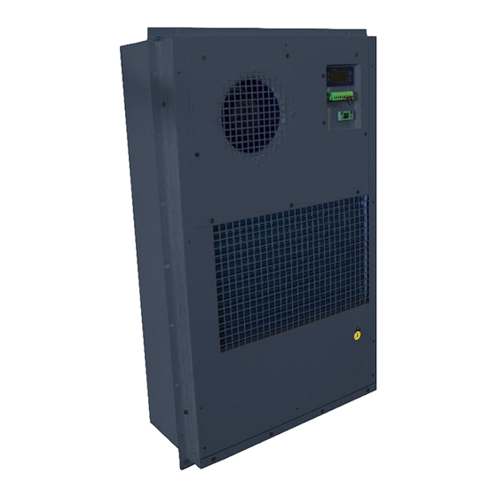
- Page 1 All manuals and user guides at all-guides.com ACT-VCC-1000 DC Cabinet Air Conditioner User Manual Read this manual carefully before installation and use.
-
Page 2: Table Of Contents
All manuals and user guides at all-guides.com Rev A (ACT-VCC-1000-DC) Summary This manual describes the ACT-VCC-1000 DC Air Conditioner and includes the product description, working principles, wiring diagrams, operating instructions, routine maintenance, troubleshooting, and technical specifications of this model. Table of Contents Summary ............................ -
Page 3: Instructions
Be sure to read this manual carefully before installing or operating the unit. • To be covered by ACT’s warranty and access normal warranty service, the user(s) must comply with all local and industry standards, as well as with the instructions in this User Manual. -
Page 4: Application Notes
All manuals and user guides at all-guides.com Rev A (ACT-VCC-1000-DC) 2.2 Application Notes This product is intended for use in industrial equipment applications that utilize a 48V DC power supply. The purpose of its installation is to control cabinet temperature between 20 to 45℃;... -
Page 5: Technical Specifications
All manuals and user guides at all-guides.com Rev A (ACT-VCC-1000-DC) 2.5 Technical Specifications Table 2.1 Technical Specifications Note: Parameters will be subject to the latest specification 2.6 Air Circulation and Remote Mounting Internal circulation and external circulation of the air is shown in Figure 2.3. Ducting and a separating plate are not required for enclosure mounting applications. -
Page 6: Operation Of The Unit
All manuals and user guides at all-guides.com Rev A (ACT-VCC-1000-DC) 2.7 Operation of the Unit When the unit is turned on, it will perform a self-test before starting standard operation. If any faults are detected during the self-test, the system goes into the ‘fault’ mode; an alarm will be triggered and an error code will be shown on the LED display to alert the user. -
Page 7: Led Display Parameter Setting Guide
*Heating functions are optional and not included on all units. The above parameters can be accessed through RS485 communication if necessary. For questions, please contact ACT’s sales staff at 717-295-6061. 2.10 Alarm and fault management During normal operation, the LED displays the return air temperature leaving the air conditioner. An alarm signal will alert the user to an error and the alarm code error message will be displayed alternately with the return air temperature. -
Page 8: Packaging And Shipping
All manuals and user guides at all-guides.com Rev A (ACT-VCC-1000-DC) Low-temperature warning DC Power overvoltage warning DC Power undervoltage warning Refrigerant circuit pressure is too high warning Refrigerant circuit pressure is too low warning E13* Heater current overload warning E14*... -
Page 9: Unpacking And Acceptance
All manuals and user guides at all-guides.com Rev A (ACT-VCC-1000-DC) 4. Unpacking and Acceptance • Make sure the package is upright as shown in Figure 4.1 before you open the package, Figure 4.1 packaging • Please check that the packing straps are unbroken and that the wooden box is undamaged, not deformed or wet. -
Page 10: Electrical Connection
All manuals and user guides at all-guides.com Rev A (ACT-VCC-1000-DC) Figure 5.2 Dimensions for cut-out in enclosure door Installation steps: 1. Mark the cabinet with the cut-out dimensions according to Figure 5.2 2. Cut out the shaded area 3. Remove the product from the shipping crate with care 4. - Page 11 All manuals and user guides at all-guides.com Rev A (ACT-VCC-1000-DC) Table 5.1: Wiring Requirements MODEL ACT-VCC-1000-DC Power supply - 48 VDC* ( GND/RTN: positive, -48: negative) Power supply range -42 VDC ~ - 60 VDC. DC power supply source capacity ≥15Amps @ 48VDC...
-
Page 12: Running And Testing
All manuals and user guides at all-guides.com Rev A (ACT-VCC-1000-DC) Figure 5.3 System wiring diagram Intfan Extfan RS485 -48V CTRL T/R- T/R+ 6. Running and Testing 6.1 Pre-operational checks After Air Conditioner is installed and the electrical connection is completed, please complete the following checklist: Table 6.1 Pre-operational checks... -
Page 13: Operating The Unit
All manuals and user guides at all-guides.com Rev A (ACT-VCC-1000-DC) 6.2 Operating the Unit Apply power to the unit. The product will first run a self-test program, and then the unit will run normally. (Self-test: Refer to “Section 2.7: Operation”) •... -
Page 14: Maintenance And Warranty
All manuals and user guides at all-guides.com Rev A (ACT-VCC-1000-DC) Setting Display Parameters: Press the "M" key for 5 seconds, causing the system to enter into parameter setting mode. The display will show the “Pxx” code. • Use arrow "" keys to choose the desired item. - Page 15 All manuals and user guides at all-guides.com Rev A (ACT-VCC-1000-DC) 7.1.3 Routine Maintenance Table 7.3 Routine maintenance NUM. Check items Check methods Solution Turn off the supply power Tug on the power line with moderate force and check Power line...
-
Page 16: Service And Repair
Other system faults 7.2 Service and Repair Warranty period: 1-year limited warranty Warranty Section from ACT’s PURCHASE ORDER TERMS AND CONDITIONS • Buyer’s Property. All drawings, tools, fixtures, materials and other items supplied or paid for by Buyer shall be and remain the property of Buyer. All such items shall be used only in the performance of work under this Order unless Buyer consents otherwise in writing. - Page 17 Payment for any Goods shall not be deemed an acceptance hereof. Please see ACT’s current full Terms & Conditions: https://www.1-act.com/termsandconditions/ Disclaimer The warranty is limited to the delivered product(s) and ACT is not responsible for any loss that may be derived by equipment failure. Questions or Comments? ACT Quality Department: quality@1-act.com...
Need help?
Do you have a question about the ACT-VCC-1000 and is the answer not in the manual?
Questions and answers