
Related Manuals for KVC KVC450


Summary of Contents for KVC KVC450
- Page 1 ( ) KVC 주 Compact Shim Vacuum Gauge User's Manual KVC450 Module http : // www.kvcins.com...
- Page 2 Thank you for purchasing the product of the company. The products of the company have been verified in the quality and performance by KVC by going through the processes of design, production and inspection of the product based on the regulations of ISO9001, and various models of products are structured to enable users select the product.
-
Page 3: Table Of Contents
( ) KVC 주 Make sure to turn on the power after checking the controller and the sensor are connected. CONTENTS 1. PRODUCT OVERVIEW ----------------------------------------------------------------------------------------- (PAGE 5 ) 2. STRUCTURE OF PRODUCT ------------------------------------------------------------------------------------ (PAGE 5 ) 3. PRODUCT FEATURES ------------------------------------------------------------------------------------------ (PAGE 5 ) - Page 4 ( ) KVC 주 7-8 Dead band setting flow 7-9 Vacuum value calibration flow 8. HOW TO SET UP AND OPERATE OF PRODUCT ------------------------------------------------------------- (PAGE 20 ) 8-1 Setting data initialize 9. COMMUNICATION FUNCTION AND SETTING OF PRODUCT ( COMMUNICATION IS OPTIONAL )
-
Page 5: Product Overview
3-3-2 You can monitoring computer control using RS485 ASCII or RS485 MODBUS communication. ( Communication is optional ) 3-3-3 KVC450 is designed to enhance reliability by using a 16 bit A/D converter with high performance and high precision. 3-3-4 All parameters can be set by front key. -
Page 6: Names Of Product Parts
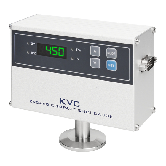
( ) KVC 주 4. NAMES OF PRODUCT PARTS 4-1 Names of front parts SP1 , SP2 LED : LED on when value is satisfied Display window : Display current vacuum value Pressure unit ( Torr or Pa ) : Default is Torr UP KEY : Used to change the setting value. -
Page 7: Connection Diagram
( ) KVC 주 4-2 Connection diagram PIN NUMBER PIN DESCRIPTION RS485- input RS485+ input Power Input ( 20 ~ 30Vdc ) Power Ground Lin scale analog output ( 0 ~ 10 Vdc between 1.0E-3 ∼ 1 Torr ) Signal Ground... -
Page 8: Product Specification
( ) KVC 주 5. PRODUCT SPECIFICATION 5-1 Controller specification MEASURING RANGE FOR AIR AND N₂ 1.0E-3 ∼ 1000 Torr OPERATING TEMPERATURE ∼ ℃ STORAGE TEMPERATURE - 40 ∼ ℃ CASE MATERIAL Aluminum COMPLIANCE CE ( EMC ) 4 Digit LED , Status LED... -
Page 9: Main Functions Of Product
( ) KVC 주 6. MAIN FUNCTIONS OF PRODUCT 6-1 Check before setting up features and precautions 6-1-1 Push at once the ▲ ▼ keys to change to the function setting mode. 6-1-2 Be sure to push SET key after setting the value. -
Page 10: Dead Band Function
( ) KVC 주 6-4 Dead band function 6-4-1 SP1, SP2 Individual Dead Band settings are available. 6-4-2 This function delays SP1 and SP2 from the set point value set by giving dead band respectively. Setting value Dead Band 0.0 % ( Default ) ... -
Page 11: Analog Output Function
( ) KVC 주 6-5 Analog output function 6-5-1 Log scale analog output 6-5-1-1 Connects to PIN NO 7, and 8. ( D-sub connector ) ☞ Refer to ( 4-2 ) Connection diagram 6-5-1-2 When Full range scale (1.0E-3 ∼... - Page 12 ( ) KVC 주 Vacuum Default value Output change by Bias Maximum output adjustment value 8 ( Vdc ) +0 ( Vdc ) : Default -3 ( Vdc ) ∼ +3 ( Vdc ) +1 ( Vdc ) -2 ( Vdc ) ∼...
-
Page 13: Initialization Function
( ) KVC 주 0.05 1 ( Torr ) 6-5-3 Cable connection method Connects to the D-sub connector 15pin for the instrument or PLC that you want to measure. ☞ Refer to ( 4-2 ) Connection diagram ) 6-6 Initiallization function ☞... - Page 14 ( ) KVC 주 p3 Log analog output bias setting ▲ p6 SP1 high/low alarm setting ▲ p7 SP2 high/low alarm setting ▲ p8 SP1 Dead band setting ▲ p9 SP2 Dead band setting ▲ Communication p1 Address setting ( Optional ) ▲...
-
Page 15: Vacuum Unit Setting Flow
( ) KVC 주 7-3 Vacuum unit setting flow VACUUM ▲ ▼ Adjust by ▲ ▼ Press at the same time. MODE p1 ▲ p2 VACUUM Pressing the SET KEY twice in a row will also display the vacuum. -
Page 16: Log Analog Output Bias Setting Flow
( ) KVC 주 Setting Operation 0.5 ( Vdc ) / Decade ( Default ) 1.0 ( Vdc ) / Decade 1 1.5 ( Vdc ) / Decade 2.0 ( Vdc ) / Decade ... -
Page 17: Alarm High / Low Setting Flow
( ) KVC 주 7-6 Alarm high / low setting flow ▲ ▼ VACUUM Press at the same time. p1 ▲ Adjust by ▲ ▼ MODE press continuously 1 p6 ▲ Adjust by ▲ ▼ MODE p7 1 ▲ p8 VACUUM Pressing the SET KEY twice in a row will also display the vacuum. -
Page 18: Set Point Setting Flow
( ) KVC 주 7-7 Set point setting flow VACUUM MODE Press for 3 to 4 seconds. SP D MODE Adjust by ▲ ▼ SP1 LED flicker 4 4 Adjust by ▲ ▼ SP2 LED flicker VACUUM Pressing the SET KEY twice in a row will also display the vacuum. - Page 19 ( ) KVC 주 Adjust by ▲ ▼ MODE P8 ▲ Adjust by ▲ ▼ MODE P9 ▲ P1 VACUUM Pressing the SET KEY twice in a row will also display the vacuum. Setting Dead Band ( Default ) 0.0 %...
-
Page 20: How To Set Up And Operate Of Product
( ) KVC 주 7-9 Vacuum value calibration setting flow 7-9-1 This function compensates for atmospheric pressure caused by prolonged use or contamination. 7-9-2 If the vacuum is 6.0E+2 in the Display window from the current atmospheric pressure, then 7.6E+2 is set when the vacuum value is corrected. -
Page 21: Communication Function And Setting Of Product ( Communication Is Optional )
( ) KVC 주 9. COMMUNICATION FUNCTION AND SETTING OF PRODUCT 9-1 Communication function 9-1-1 Communication is selected by the user's order. 9-1-2 The communication methods are RS48 ASCII and RS485 MODBUS. 9-1-3 Connected units : RS485 ASCII ----> Max 16 units / RS485 MODBUS ----> Max 32 units 9-1-4 Both ASCII, MODBUS require communication address to be set up. -
Page 22: Communication Setting Flow
( ) KVC 주 9-2 Communication setting flow VACUUM ▲ ▼ Press at the same time. p1 ▲ Adjust by ▲ ▼ MODE press continuously p1 Address ▲ Adjust by ▲ ▼ MODE p11 9 Baud rate ▲ p12 VACUUM Pressing the SET KEY twice in a row will also display the vacuum. -
Page 23: Dimension Of Product
( ) KVC 주 10. DIMENSION OF PRODUCT 10-1 Controller dimension 10-2 Sensor dimension SENSOR is a convection type to measure the correct value at a pressure of 1 Torr or higher. It must be installed horizontally. http : // www.kvcins.com... -
Page 24: Manual Related To Communication Of Product
( ) KVC 주 11. MANUAL RELATED TO COMMUNICATION OF PRODUCT -1 RS485 ASCII Communication 11-1-1 Communication specification 11-1-1-1 Communication method : RS485 2 Wire half duplex 11-1-1-2 Communication baud rate : 4800 ∼ 115,200 bps ( Default : 115200 bps ) - Page 25 ( ) KVC 주 DATA : D1 Dn … Virtual data is going. If size is 0, it may not be existed. 1Byte, packet end code 0x03h CHECK SUM : BCC BCC = ASCII value( ( STX + … + ETX ) & 0x0F )
-
Page 26: Rs485 Modbus Communication
( ) KVC 주 11-1-3-2 Alarm data setting command ( Command to read the setting point value ) MENU COMMAND DATA RESPONSE DATA “d.dE±dd" Alarm 1 value setting “10” Alarm 2 value setting “11” “d.dE±dd" 11-1-3-3 UNIT Change Command MENU... - Page 27 ( ) KVC 주 Error ( Slave ----> Master ) 0x01 0x83 Response Address Exception code CRC 16 command ( Exception codes ) 0x01 : Command code not supported. 0x02 : When the address of the requested data is different from the address that can be transmitted by the unit.
- Page 28 ( ) KVC 주 11-2-2-3 Function code 6 ( 0x06 ) : Write single resisters Request ( Master ----> Slave ) 0x01 0x06 0x00 0x00 0x03 0xE8 Address Data CRC 16 Address Command H byte L byte H byte L byte...
- Page 29 ( ) KVC 주 rror ( Slave ----> Master ) 0x01 0x90 Response Address Exception code CRC 16 command ( Exception code ) 0x01 : Command code not supported. 0x02 : When the address of the requested data is different from the address that can be transmitted by the unit.
-
Page 30: Fittings
( ) KVC 주 12. FITTINGS 13. 7-SEGMENT LED DISPLAY OF ALPHA-NUMERIC WORDS WORD 7-SEG. WORD 7-SEG. WORD 7-SEG. WORD 7-SEG. http : // www.kvcins.com... -
Page 31: Rs485 Multi Communication Connecting Method
( ) KVC 주 14. RS485 MULTI COMMUNICATION CONNECTING METHOD TOUCH RS485 PORT ADAPTER Connect 500 Ω of terminal Connect 500 Ω of terminal resistance between resistance between communication lines communication lines ( + ) and ( - ) ( + ) and ( - ) -
Page 32: Troubleshooting
( ) KVC 주 15. TROUBLESHOOTING Overloaded performance of tasks can be dangerous. Only those acknowledged in the performance ability should use the product. Make sure to always turn off input power before any operations. When the product has been disassembled by a user’s decision, the company or the distributor of the product does not have any liability on quality assurance even if effective warranty period remains. - Page 33 ( ) KVC 주 15-5 Set point is satisfied but alarm relay is not operating : 15-5-1 Check whether the SP1 led or SP2 led is illuminated on the front of the controller. 15-5-2 Check the Alarm high / low settings. ( ☞...
-
Page 34: Sensor Replacement Method
( ) KVC 주 16. SENSOR REPLACEMENT METHOD 16-1 Replace the sensor according to the following procedure. ( Be sure to remove the power when replacing. ) SIDE PCB ASSY A : SIDE CASE B : SIDE CASE C : SENSOR... -
Page 35: Warranty
( ) KVC 주 17. WARRANTY 17-1 The warranty period of this product is one year. ( There is no warranty period for sensors which are consumables. ) 17-2 If any failures occur in normal use of the product during warranty period, repair will be provided without any charges. -
Page 36: Annex ( Table Of Range Of Measurements For Each Vacuum Gauge Models Of The Company )
⁻ ⁻ 100 760 1000 1500 KP100 KM700 KP120 KVC2300 , KVC3300 , KVC4000 KP360 , KP370 , KP380 KP390 KC430 , KVC450 KPM200, KVC460, KVC2500, KVC4000 ATM CDM600 CDM610 KIM800 KPM550 KPM560 KVC5000, KVC5000 ATM KVC900, KVC900 ATM http : // www.kvcins.com...
Need help?
Do you have a question about the KVC450 and is the answer not in the manual?
Questions and answers