Table of Contents
Advertisement
Advertisement
Table of Contents

Related Manuals for KVC KP390


Summary of Contents for KVC KP390
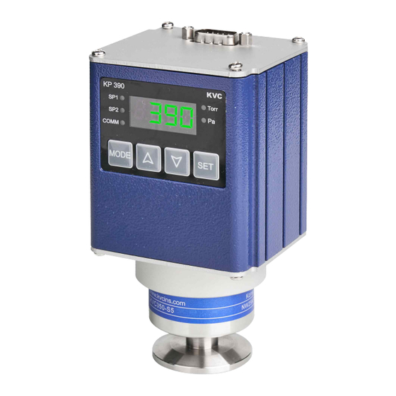
- Page 1 Mirco Vacuum Gauge User's Manual KP390 Module http : // www.kvcins.com...
- Page 2 Thank you for purchasing the product of the company. The products of the company have been verified in the quality and performance by KVC by going through the processes of design, production and inspection of the product based on the regulations of ISO9001, and various models of products are structured to enable users select the product.
-
Page 3: Table Of Contents
Make sure to turn on the power after checking the controller and the sensor are connected. CONTENTS 1. PRODUCT OVERVIEW ------------------------------------------------------------------------------------------- (PAGE 5 ) 2. STRUCTURE OF PRODUCT -------------------------------------------------------------------------------------- (PAGE 5 ) 3. PRODUCT FEATURES -------------------------------------------------------------------------------------------- (PAGE 5 ) 3-1 Range of vacuum measurement of product 3-2 Display state of product 3-3 Features and functions of product 4. - Page 4 8. HOW TO SET UP AND OPERATE OF PRODUCT ------------------------------------------------------------- (PAGE 17 ) 8-1 Setting data initialize 9. COMMUNICATION FUNCTION AND SETTING OF PRODUCT ( COMMUNICATION IS OPTIONAL ) ---- (PAGE 17 ) 9-1 Communication function 9-2 Communication setting flow 10.
-
Page 5: Product Overview
3-2-3 If the Sensor is not connected, is displayed. 3-3 Features and functions of product 3-3-1 KP390 is designed to enhance reliability by using a 16 bit A/D converter with high performance and high precision. 3-3-2 The two relay contact outputs are fitted by default. -
Page 6: Names Of Product Parts
4. NAMES OF PRODUCT PARTS 4-1 Names of front parts ☞ D-sub 15pin connector : For external connection ( Refer to ( 4-2 ) Connection diagram ) Display window : Display current vacuum value SP1 , SP2 LED : LED on when value is satisfied COMM LED : Communication operation status LED MODE KEY : Menu Step Move Key UP KEY : Used to change the setting value. -
Page 7: Connection Diagram
4-2 Connection diagram PIN NUMBER PIN DESCRIPTION RS485- input RS485+ input Power Input ( 20 ~ 30Vdc ) Power Ground Log scale analog output ( 0 ~ 7.18 Vdc for full range ) Signal Ground Signal Ground Lin scale analog output ( 0 ~ 10 Vdc between 1.0E-4 ∼ 1 Torr ) No connection Relay1 Normally Open Relay2 Normally Open... -
Page 8: Product Specification
5. PRODUCT SPECIFICATION 5-1 Controller specification MEASURING RANGE FOR AIR AND N₂ 1.0E-4 ∼ 1500 Torr OPERATING TEMPERATURE 0 ∼ 60 ℃ STORAGE TEMPERATURE - 40 ∼ 70 ℃ CASE MATERIAL Aluminum COMPLIANCE 4 Digit LED , Status LED DISPLAY SET POINT RELAYS 2 Point SPST ( 1A / 30VDC , 0.5A / 125VAC ) Log scale ( 0 ∼... -
Page 9: Main Functions Of Product
6. MAIN FUNCTIONS OF PRODUCT 6-1 Check before setting up features and precautions 6-1-1 Push at once the ▲ and ▼ keys to change to the function setting mode. 6-1-2 Be sure to push SET key after setting the value. ( If the key is not pushed, the set value cannot be saved.) 6-2 Set point function 6-2-1 Standard relay 2-set point ( It control of Vacuum pump on/off and Valve on/off. -
Page 10: Dead Band Function
6-4 Dead band function 6-4-1 You can set it from 00 to 99%. 6-4-2 Default is 10 % 6-5 Analog output function 6-5-1 Log scale output 6-5-1-1 When Full range scale (1.0E-4 ∼ 1500 Torr), the analog output is from 0 ∼ 7.18 Vdc. 6-5-1-2 Connects to PIN NO 5, and 6. -
Page 11: Initialization Function
6-5-2 Lin scale output 6-5-2-1 When 1.0E-4 ∼ 1 Torr, the analog output is from 0 ∼ 10 Vdc. 6-5-2-2 Connects to PIN NO 7, and 8. ( D-sub connector ) ☞ Refer to ( 4-2 ) Connection diagram ) 6-5-2-3 Analog output value 절대압(Torr) N2/Air(Vdc) -
Page 12: Parameter Setting Of Product
7. PARAMETER SETTING OF PRODUCT 7-1 Setting method 7-1-1 Push at once the ▲ and ▼ keys to change to the function setting mode. 7-1-2 To exit the MODE function during setup, keep pushing the SET key until the vacuum value is displayed. 7-2 Setting flow Push the SET key to release from the Mode function VACUUM... -
Page 13: Vacuum Unit Setting Flow
Communication Ad-d Address setting ( Optional ) MODE Communication bA-d Baud rate setting (Optional) MODE Atmospheric pressure correction At-M MODE Vacuum value correction vA-C VACUUM 7-3 Vacuum unit setting flow VACUUM ▲ ▼ Press at the same time. SM-d MODE Adjust by ▲,▼... -
Page 14: Alarm High / Low And Dead Band Setting Flow
7-4 Alarm high / low and Dead band setting flow ☞ For setting values, Refer to (6-3) Alarm high / low function VACUUM and (6-4) Dead band function ▲ ▼ Press at the same time SM-d MODE Adjust by ▲,▼ ▲... -
Page 15: Set Point Setting Flow
7-5 Set point setting flow VACUUM MODE Adjust by ▲,▼ ▲ ▼ Set point 1 SP-1 10-4 setting MODE MODE Adjust by ▲,▼ ▲ ▼ Set point 2 SP-2 10-4 setting MODE MODE press continuously VACUUM 7-6 Analog output setting flow VACUUM If the Sensor is not connected, is displayed. -
Page 16: Atmospheric Pressure And Vacuum Calibration Flow
MODE MODE press continuously VACUUM 7-7 Atmospheric pressure and Vacuum calibration flow VACUUM ▲ ▼ Press at the same time SM-d MODE Adjust by ▲,▼ Atmospheric ▲ ▼ pressure At-M correction MODE MODE Adjust by ▲,▼ ▲ ▼ Vacuum vA-C correction MODE MODE... -
Page 17: How To Set Up And Operate Of Product
8. HOW TO SET UP AND OPERATE OF PRODUCT 8-1 Setting data initialize 8-1-1 Initialization function 8-1-1-1 Turn off the power and press at the same time MODE + SET key and turn the power on. 8-1-1-2 After a while, release the key if IN-T is displayed in . -
Page 18: Communication Setting Flow
9-2 Communication setting flow VACUUM ▲ ▼ Press at the same time. SM-d MODE Adjust by ▲,▼ ▲ ▼ Ad-d Address setting MODE MODE Adjust by ▲,▼ ▲ ▼ Baud rate bA-d 38-4 setting MODE MODE press continuously VACUUM http : // www.kvcins.com... -
Page 19: Dimension Of Product
10. DIMENSION OF PRODUCT 10-1 Controller dimension ( w / sensor ) Be sure the vacuum gauge and the rest of your vacuum system are properly grounded to protect personnel from shock and injury. Do not mount this gauge where it will be subjected to excessive vibration, such as on mechanical pumps. -
Page 20: Manual Related To Communication Of Product
11. MANUAL RELATED TO COMMUNICATION OF PRODUCT 11-1 RS485 ASCII Communication 11-1-1 Communication specification 11-1-1-1 Communication method : RS485 2 Wire half duplex 11-1-1-2 Communication baud rate : 4800, 9600, 19200, 38400 bps ( Default : 38400 bps 11-1-1-3 Data length : 8 Bit 11-1-1-4 Stop bit : 1 Bit 11-1-1-5 Parity : None 11-1-1-6 Connected units : Max 16 units... - Page 21 DATA : D1…Dn Virtual data is going. If size is 0, it may not be existed. 1Byte, packet end code 0x03h CHECK SUM : BCC BCC = ASCII value( ( STX +… + ETX ) & 0x0F ) ( Ex ) Reading the current vacuum ( If device number is 00 ) CMDH CMDL ‘0’...
-
Page 22: Rs485 Modbus Communication
11-1-3-2 Alarm data setting command ( Command to read the setting point value ) MENU COMMAND DATA RESPONSE DATA “d.dE±dd" SP1 value setting “11” SP2 value setting “12” “d.dE±dd" 11-1-3-3 Unit Request MENU COMMAND DATA RESPONSE DATA "0" : Torr Unit request “20”... - Page 23 Response ( Slave ----> Master ) 0x01 0x03 0x10 0x03 0xE8 0x03 0xE8 First Data n th Data CRC 16 Respond No. of Address command Data H byte L byte H byte L byte H byte L byte Error ( Slave ----> Master ) 0x01 0x83 Response...
- Page 24 ( Exception code ) 0x01 : Command code not supported. 0x02 : When the address of the requested data is different from the address that can be transmitted by the unit. 0x03 : When the number of requested data is larger than the number that can be transmitted by the unit. 0x04 : When transmitted data is not treated correctly.
- Page 25 11-2-2-4 Function code 16 ( 0x10 ) : Write multiple registers Request ( Master ----> Slave ) 0x01 0x10 0x00 0x00 0x00 0x10 0x20 0x03 0xE8 Starting address No. of Data Data CRC 16 Comma Byte ress H byte L byte H byte L byte H byte...
- Page 26 11-2-3 Address mapping table 11-2-3-1 Input registers ADDRESS ITEM DATA 30001 (0000) Current Vacuum value LOG(Vacuum) * 1000 30002 (0001) LOG out voltage Voltage * 100 30003 (0002) LIN out voltage Voltage * 100 0 : all off 1 : SP1 on 30004 (0003) Alarm status 2 : SP2 on...
-
Page 27: Fittings
12. FITTINGS ( Please contact us when using the fitting ) 13. 7-SEGMENT LED DISPLAY OF ALPHA-NUMERIC WORDS WORD 7-SEG. WORD 7-SEG. WORD 7-SEG. WORD 7-SEG. http : // www.kvcins.com... -
Page 28: Rs485 Multi Communication Connecting Method
14. RS485 MULTI COMMUNICATION CONNECTING METHOD TOUCH RS485 PORT ADAPTER Connect 500Ω of terminal Connect 500Ω of terminal resistance between resistance between communication lines communication lines ( + ) and ( - ) ( + ) and ( - ) ( CONTROLLER ) ( CONTROLLER ) ( CONTROLLER ) -
Page 29: Troubleshooting
15. TROUBLESHOOTING Overloaded performance of tasks can be dangerous Only those acknowledged in the performance ability should use the product. Make sure to always turn off input power before any operations. When the product has been disassembled by a user’s decision, the company or the distributor of the product does not have any liability on quality assurance even if effective warranty period remains. -
Page 30: Warranty
15-6 n case of severe vacuum error when using analog output : 15-6-1 Use DVM (Digital voltage meter) to measure analog out and contact us if linearity is not good. 15-7 If RS232 / RS485 communication failure occurs : 15-7-1 Check the connection state of communication cables and check if the connecting pin is normal. 15-7-2 ( ☞... -
Page 31: Annex ( Table Of Range Of Measurements For Each Vacuum Gauge Models Of The Company )
10⁻⁹ 10⁻⁸ 10⁻⁷ 10⁻⁶ 10⁻⁵ 10⁻⁴ 10⁻³ 10⁻² 10⁻¹ 100 760 1000 1500 KP100 KM700 KP120 KVC2300 , KVC3300 , KVC4000 KP360 , KP370 , KP380 KP390 KC430 , KVC450 KPM200, KVC460, KVC2500, KVC4000 ATM CDM600 CDM610 KIM800 KPM550 KPM560...
Need help?
Do you have a question about the KP390 and is the answer not in the manual?
Questions and answers