
Related Manuals for KVC KM700N


Summary of Contents for KVC KM700N
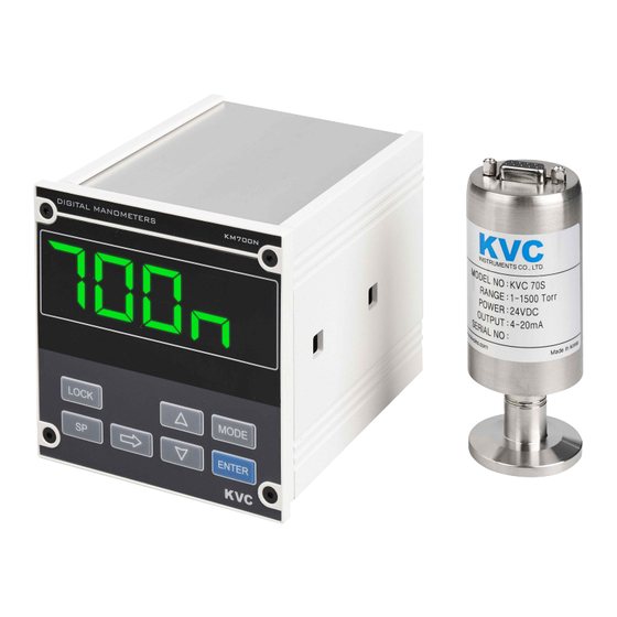
- Page 1 Digital Manometer Vacuum Gauge User's Manual KM700N Controller http : // www.kvcins.com...
- Page 2 Thank you for purchasing the product of the company. The products of the company have been verified in the quality and performance by KVC by going through the processes of design, production and inspection of the product based on the regulations of ISO9001, and various models of products are structured to enable users select the product.
-
Page 3: Table Of Contents
Make sure to turn on the power after checking the controller and the sensor are connected. CONTENTS 1. PRODUCT OVERVIEW ----------------------------------------------------------------------------------------- (PAGE 5 ) 2. STRUCTURE OF PRODUCT ------------------------------------------------------------------------------------ (PAGE 5 ) 3. PRODUCT FEATURES ------------------------------------------------------------------------------------------ (PAGE 5 ) 3-1 Range of vacuum measurement of product 3-2 Display state of product 3-3 Features and functions of product 4. - Page 4 8. HOW TO SET UP AND OPERATE OF PRODUCT ------------------------------------------------------------- (PAGE 17 ) 8-1 Fuse replacement method 8-2 Setting data initialize 8-3 Key lock function 9. COMMUNICATION FUNCTION AND SETTING OF PRODUCT ( COMMUNICATION IS OPTIONAL ) ---- (PAGE 18 ) 9-1 Communication function 9-2 Communication setting flow 10.
-
Page 5: Product Overview
) when range is lower. 3-3 Features and functions of product 3-3-1 KM700N is designed to enhance reliability by using a 16 bit A/D converter with high performance and high precision. 3-3-2 The two relay contact outputs are fitted by default. -
Page 6: Names Of Product Parts
4. NAMES OF PRODUCT PARTS 4-1 Names of front parts Display window : Display current vacuum value SP1 , SP2 LED : LED on when value is satisfied LOCK KEY : Enable or disable for front panel key SP KEY : When adjust the SP1 and SP2 value. SHIFT KEY : Unit shift key. -
Page 7: Names Of Rear Parts
4-2 Names of rear parts Accessory Port : A/O , SP1 , SP2 , Sensor , Communication Port ☞ Refer to ( 4-3 ) Connection diagram ) Fuse Holder : Main fuse and spare fuse Power Inlet : Input power ( 85VAC ∼ 260Vac Free voltage ) Ground http : // www.kvcins.com... -
Page 8: Connection Diagram
4-3 Connection diagram PIN NO DESCRIPTION Sensor power DC24V / 30 ㎃ ----------> Red color 4 ∼ 20 ㎃ input ( Return)signal -----------> Black color Shield -----> Green color Analog output ( + ) Analog output ( - ) RS232 RX / RS485 ( + ) RS232 TX / RS485 ( - ) GROUND ( Communication ) Setpoint 1 output... -
Page 9: Product Specification
5. PRODUCT SPECIFICATION 5-1 Controller specification MEASURING RANGE FOR AIR AND N₂ 1 ∼ 1500 Torr OPERATING TEMPERATURE 0 ∼ 60 ℃ STORAGE TEMPERATURE - 40 ∼ 70 ℃ CASE MATERIAL Aluminum or Plastic COMPLIANCE CE ( EMC ) 4Digit LED, Status LED DISPLAY SET POINT RELAYS 2Point SPST ( 5A / 250VAC, 5A / 30VDC ) -
Page 10: Main Functions Of Product
6. MAIN FUNCTIONS OF PRODUCT 6-1 Check before setting up features and precautions 6-1-1 Be sure to turn off the LOCK LED before setting the function. 6-1-2 Push the LOCK key for 3 ∼ 5sec to release LOCK LED. 6-1-3 Push at once the ▲ and ▼ keys to change to the function setting mode. 6-1-4 Push the LOCK key for release on the way setting. -
Page 11: Analog Output Function
6-4 Analog output function 6-4-1 Log scale output Log ( Pvac ) = Analog output ( VDC ) Vacum value 1500 Torr 1000 Torr 100 Torr 10 Torr 1 Torr Output ( 0 LOG ) 3.18 Vdc 3.00 Vdc 2.00 Vdc 1.00 Vdc 0 Vdc Output ( 1 LOG ) -
Page 12: Parameter Setting Of Product
7. PARAMETER SETTING OF PRODUCT 7-1 Setting method 7-1-1 Push the LOCK key for 3 ∼ 5sec to release LOCK LED. 7-1-2 Push at once the ▲ and ▼ keys to change to the function setting mode. 7-1-3 To exit the MODE function during setup, keep pushing the ENTER key. 7-2 Setting flow VACUUM ▲... -
Page 13: Vacuum Unit Setting Flow
Communication address seting MODE bAUD Comunication baud rate setting MODE VACUUM Communiation is optional 7-3 Vacuum unit setting flow 7-3-1 This mode sets the unit of vacuum value display in Torr or KPa. VACUUM ▲ ▼ Press at the same time pa-M MODE Adjust by ▲,▼... -
Page 14: Alarm High / Low Setting Flow
7-4 Alarm high / low setting flow 7-4-1 This function sets the alarm type to the high/low VACUUM ▲ ▼ Press at the same time pa-M MODE Adjust by ▲,▼ → s1MD MODE MODE Adjust by ▲,▼ → s2MD MODE MODE VACUUM http : // www.kvcins.com... -
Page 15: Set Point Setting Flow
7-5 Set point setting flow VACUUM SP1, SP2 can be set between 0000 and 1500 MODE Adjust by ▲,▼ → 0010 sP-1 MODE MODE Adjust by ▲,▼ → sP-2 0010 MODE VACUUM 7-6 Analog output value check flow VACUUM MODE →... -
Page 16: Bias Value And Analog Output Setting Flow
7-7 Bias value and analog output setting flow VACUUM Output can be set at 0 Log, 1 Log , 0 Lin, 1 Lin ▲ ▼ Press at the same time pa-M MODE Adjust by ▲,▼ → 0000 BIAS MODE MODE Adjust by ▲,▼... -
Page 17: How To Set Up And Operate Of Product
8. HOW TO SET UP AND OPERATE OF PRODUCT 8-1 Fuse replacement method ☞ Pull out the fuse holder as shown in the figures. Replace the spare fuse in the holder FUSE SPEC. : 250Vac/1A 8-2 Setting data initialize 8-2-1 Turn off the power and press at the same time MODE + ENT key and turn the power on. 8-2-2 After a while, release the key if IN-T is displayed in . -
Page 18: Communication Function And Setting Of Product ( Communication Is Optional )
9. COMMUNICATION FUNCTION AND SETTING OF PRODUCT ( ☞ Refer to 11 ) 9-1 Communication function 9-1-1 The communication method is RS232 and RS485 half duplex and is determined by the user's choice when ordering. 9-1-2 RS232 / RS485 communications have ASCII or MODBUS methods, respectively. 9-1-3 Both RS232, RS485 require communication address to be set up. -
Page 19: Dimension Of Product
10. DIMENSION OF PRODUCT 10-1 Controller dimension 10-2 Sensor dimension Be sure to remove the AC power cord and replace it when replacing sensor. ( Open circuits and malfunctions in sensor may occur. ) http : // www.kvcins.com... -
Page 20: Manual Related To Communication Of Product
11. MANUAL RELATED TO COMMUNICATION OF PRODUCT -1 RS232 / RS485 ASCII Communication 11-1-1 Communication specification 11-1-1-1 Communication method : RS232 3 Wire / RS485 2 Wire half duplex 11-1-1-2 Communication baud rate : 4800, 9600, 19200, 38400 bps ( Default : 38400 bps 11-1-1-3 Data length : 8 Bit 11-1-1-4 Stop bit : 1 Bit... - Page 21 DATA : D1…Dn Virtual data is going. If size is 0, it may not be existed. 1Byte, packet end code 0x03h CHECK SUM : BCC BCC = ASCII값( ( STX +… + ETX ) & 0x0F ) ( Ex ) Reading the current vacuum ( If device number is 01 ) CMDH CMDL ‘0’...
- Page 22 11-1-3-3 Setting parameter request command ( Read the setting parameter value ) MENU COMMAND DATA RESPONSE DATA "0" : Manometer Input type “21” “d” "1" : ㎃ Input "0" : Torr Unit “22” “d” "1" : KPa Input H-Range “23” “±ddd.d”...
- Page 23 11-1-4-2 Parameter set Command ( Write the parameter value ) MENU COMMAND DATA RESPONSE DATA "0" : Manometer Input type request “61” "d" "OK" "1" : ㎃ Input "0" : Torr Unit request “62” "d" "OK" "1" : KPa “±ddd.d” Input H-Range request “63”...
-
Page 24: Rs232 / Rs485 Modbus Communication
11-2 RS232 / RS485 MODBUS Communication 11-2-1 Communication specification 11-2-1-1 Communication method : RS232 3 Wire / RS485 2 Wire half duplex 11-2-1-2 Communication baud rate : 4800, 9600, 19200, 38400 bps ( Default : 38400 bps 11-2-1-3 Data length : 8 Bit 11-2-1-4 Stop bit : 1 Bit 11-2-1-5 Parity : Even 11-2-1-6 Connected units : RS232 ---->... - Page 25 11-2-2-2 Function code 4 ( 0x04 ) : Read input resisters Request ( Master ----> Slave ) 0x01 0x04 0x00 0x00 0x00 0x10 Starting address No. of Data CRC 16 Address Command H byte L byte H byte L byte H byte L byte Response ( Slave ---->...
- Page 26 Error ( Slave ----> Master ) 0x01 0x86 Response Address Exception code CRC 16 command ( Exception code ) 0x01 : Command code not supported. 0x02 : When the address of the requested data is different from the address that can be transmitted by the unit.
- Page 27 11-2-3 Address mapping table 11-2-3-1 Input resisters ADDRESS ITEM DATA kPa: Current Vacuum value*10 30001 (0000) Current Vacuum value Torr: Current Vacuum value 30002 (0001) Output voltage Voltage * 100 First Byte 0 : SP1 off 1 : SP1 on 30003 (0002) Alarm status Second Byte...
-
Page 28: Fittings
12. FITTINGS ( KM700N CONTROLER does not support 1.33CF fitting. ) WORD 7-SEG. WORD 7-SEG. WORD 7-SEG. WORD 7-SEG. ORDS http : // www.kvcins.com... -
Page 29: Rs485 Multi Communication Connecting Method
14. RS485 MULTI COMMUNICATION CONNECTING METHOD http : // www.kvcins.com... -
Page 30: Troubleshooting
TOUCH Connect 500Ω of terminal Connect 500Ω of terminal resistance between resistance between RS485 PORT ADAPTER communication lines communication lines ( + ) and ( - ) ( + ) and ( - ) ( CONTROLLER ) ( CONTROLLER ) ( CONTROLLER ) SET NO 0 SET NO 0... - Page 31 Overloaded performance of tasks can be dangerous. Only those acknowledged in the performance ability should use the product. Make sure to always turn off input power before any operations. When the product has been disassembled by a user’s decision, the company or the distributor of the product does not have any liability on quality assurance even if effective warranty period remains.
-
Page 32: Warranty
15-5-1 Check whether the SP1 led or SP2 led is illuminated on the front of the controller. 15-5-2 Check the Alarm high / low settings. ( ☞ Refer to ( 7-4 ) Alarm high / low setting flow ) 15-6 n case of severe vacuum error when using analog output : 15-6-1 Use DVM (Digital voltage meter) to measure analog out and contact us if linearity is not good. - Page 33 ( Torr ) 10⁻¹⁰ 10⁻⁹ 10⁻⁸ 10⁻⁷ 10⁻⁶ 10⁻⁵ 10⁻⁴ 10⁻³ 10⁻² 10⁻¹ 100 760 1000 1500 KP100 KM700 KP120 KVC2300 , KVC3300 , KVC4000 KP360 , KP370 , KP380 KP390 KC430 , KVC450 KPM200, KVC460, KVC2500, KVC4000 ATM CDM600 CDM610 KIM800 KPM550...
Need help?
Do you have a question about the KM700N and is the answer not in the manual?
Questions and answers