Rinnai I Series Commissioning Manual
Hide thumbs
Also See for I Series:
- Installation and operation manual (137 pages) ,
- Instruction manual (72 pages) ,
- Conversion manual (24 pages)
Table of Contents
Advertisement
Quick Links
Advertisement
Table of Contents

Subscribe to Our Youtube Channel
Related Manuals for Rinnai I Series


Summary of Contents for Rinnai I Series
- Page 1 Rinnai I-Series Commissioning Guide...
-
Page 2: Table Of Contents
Contents 1.0 Commissioning ..................3 1.1 Pre Commissioning ....................3 1.2 Filling the System with Water ..................3 1.3 Deaeration Function ....................4 2.0 Operation ....................5 2.1 Control Panel Navigation ................... 5 2.1 Display Identification ....................6 3.0 Connection of External Accessories ............7 3.1 Connection of an External Thermostat ............... -
Page 3: Commissioning
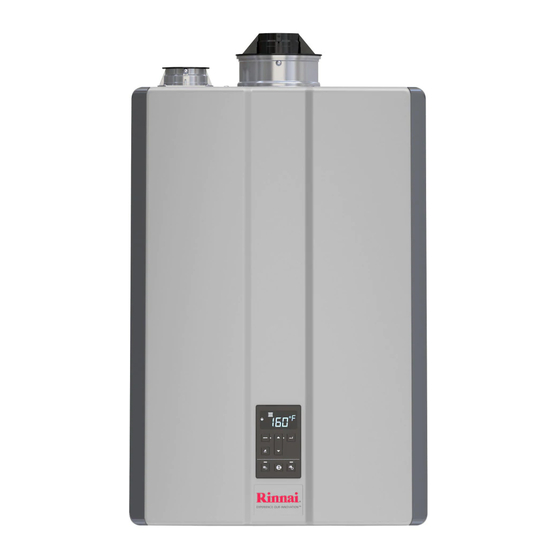
1.0 Commissioning This document must be read in conjunction with the I-Series Boiler Installation Manual provided with the unit. It is essential the manual is read and followed to ensure the installation is as per manufacturer’s specification. The purpose of this document is to assist with the commissioning of the boiler and parameters and connection of third- party controls. -
Page 4: Deaeration Function
1.3 Deaeration Function From The Boiler Control Panel The boiler deaeration function can be enabled by pressing and holding the DHW • button then simultaneously press the CH button on the control panel (shown below). The deaeration function will last approximately 15 minutes and the boiler display •... -
Page 5: Operation
2.0 Operation 2.1 Control Panel Navigation 1. MODE: Select various boiler settings. 2. UP/DOWN ARROWS: Scrolls through available menu options including adjusting the temperature. 3. ECO: Selects Eco or Comfort operation mode. 4. CENTRAL HEATING (CH): From the factory, this option is turned off by default. The boiler runs off thermostat inputs on the control board. -
Page 6: Display Identification
2.1 Display Identification 1. MAINTENANCE MODE ICON: Appears when the boiler is in Parameter Settings Mode, Deaeration Mode, Performance Data Mode, Error History Mode, etc. 2. ECO SETTING ACTIVE: Eco maintains temperature in the primary heat exchanger to provide quicker delivery of hot water to fixtures. 3. -
Page 7: Connection Of External Accessories
3.0 Connection of External Accessories The Rinnai I-Series can be configured to use an external thermostat for heating control, control additional circulating pumps and accept an outdoor sensor. Follow the below instructions regarding connection and configuration. 3.1 Connection of an External Thermostat External thermostats using volt free normally open (NO) contacts should be connected to terminals T/T (Terminal #4) found at the bottom of the boiler PCB. -
Page 8: Parameters And Features
4.0 Parameters and Features 4.1 PCB and DIP Switches Identification To access the PCB, remove the boiler’s front panel by removing the four screws that secure the panel in place. Use the diagram below to identify buttons and DIP switches Item # PCB Button Primary Function... -
Page 9: Dip Switch Settings
4.2 DIP Switch Settings DIP Switch Function Description OFF (default) Enables or disables Outdoor Outdoor Outdoor Temperature Temperature Temperature Outdoor Temperature Sensor Sensor not in use Sensor in use Sensor Central Heating Changes the mode Thermostat between external butt on used. Thermostat usage Thermostat control or... -
Page 10: Accessing Boiler Parameters
4.3 Accessing Boiler Parameters To access the parameters available on the boiler display, follow the below steps. 1. Remove the boiler’s front panel by removing the four screws that secure the panel. 2. Locate the PCB (Lower left side of unit) 3. -
Page 11: List Of Key Parameters
4.4 List of Key Parameters Below is a list of key parameters identified by CHNZ to suit most standard boiler installations. For more bespoke control and fine tuning of specific parameters please reference the full I-Series manual 8.6.2 Parameter Settings Table. Parameter # Description Default... -
Page 12: Errors And Troubleshooting
Parameter # Description Default Set To Outdoor Climatic Curve Control This parameter is available when Dip Switch 1 is in the ON position. Select the appropriate curve below. Curve 1: Standard fan coils, radiators. Based on Curve 2: Underfloor Heating. Curve 1 emitter type Curve 3: High temperature fan coil or...
Need help?
Do you have a question about the I Series and is the answer not in the manual?
Questions and answers