
Related Manuals for H3C S7500X-G Series


Summary of Contents for H3C S7500X-G Series
- Page 1 H3C S7500X-G Switch Series Hardware Information and Specifications New H3C Technologies Co., Ltd. http://www.h3c.com Document version: 6W100-20230301...
- Page 2 The information in this document is subject to change without notice. All contents in this document, including statements, information, and recommendations, are believed to be accurate, but they are presented without warranty of any kind, express or implied. H3C shall not be liable for technical or editorial errors or omissions contained herein.
- Page 3 Preface This document describes hardware information and specifications for H3C S7500X-G switch series, including chassis views and technical specifications, FRUs and compatibility matrixes, LEDs, and cables. This preface includes the following topics about the documentation: • Audience. • Conventions. •...
- Page 4 Convention Description Multi-level menus are separated by angle brackets. For example, File > Create > > Folder. Symbols Convention Description An alert that calls attention to important information that if not understood or followed WARNING! can result in personal injury. An alert that calls attention to important information that if not understood or followed CAUTION: can result in data loss, data corruption, or damage to hardware or software.
- Page 5 It is normal that the port numbers, sample output, screenshots, and other information in the examples differ from what you have on your device. Documentation feedback You can e-mail your comments about product documentation to info@h3c.com. We appreciate your comments.
-
Page 6: Table Of Contents
Contents 1 Chassis views and technical specifications ·············································· 1-1 Chassis views ················································································································································· 1-1 S7503X-G ··············································································································································· 1-1 S7503X-M-G ··········································································································································· 1-2 S7506X-G ··············································································································································· 1-2 S7506X-G-PoE ······································································································································· 1-3 S7510X-G ··············································································································································· 1-4 S7510X-G-PoE ······································································································································· 1-5 Weights and dimensions ································································································································· 1-5 Module power consumption ···························································································································· 1-8 Card power consumption ························································································································... -
Page 7: Chassis Views And Technical Specifications
Chassis views and technical specifications The S7500X-G switch series includes the models in Table1-1. Table1-1 Switch models Model Description S7503X-G H3C S7503X-G Ethernet switch chassis S7503X-M-G H3C S7503X-M-G Ethernet switch chassis S7506X-G H3C S7506X-G Ethernet switch chassis S7506X-G-PoE H3C S7506X-G-POE Ethernet switch chassis... -
Page 8: S7503X-M-G
S7503X-M-G Figure1-2 S7503X-M-G front panel (1) Power module section (2) MPU section (3) MPU section/interface module section (You can install an MPU or interface module in this slot) (4) Interface module section (5) Fan tray section S7506X-G Figure1-3 S7506X-G front panel (1) Interface module sections (2) MPU section (3) Power module sections... -
Page 9: S7506X-G-Poe
S7506X-G-PoE Figure1-4 S7506X-G-PoE front panel (1) Interface module sections (2) MPU section (3) Power module sections (4) Fan tray section... -
Page 10: S7510X-G
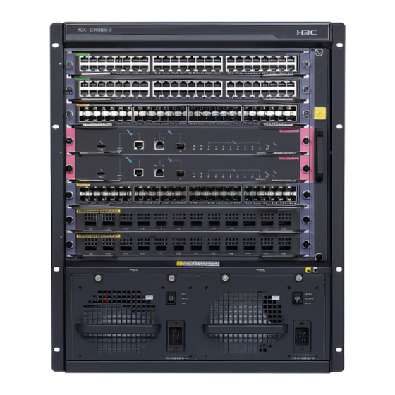
S7510X-G Figure1-5 S7510X-G front panel (1) Interface module sections (2) MPU section (3) Power module sections (4) Fan tray section... -
Page 11: S7510X-G-Poe
S7510X-G-PoE Figure1-6 S7510X-G-PoE front panel (1) Interface module sections (2) MPU section (3) Power module sections (4) Fan tray section Weights and dimensions Table1-2 Chassis weights and dimensions Weight (fully Model Height Width Depth configured) S7503X-G < 35 kg (77.16 lb) 216 mm (8.50 in)/5 RU 436 mm (17.17 in) 420 mm (16.54 in) - Page 12 Weight (fully Model Height Width Depth configured) S7510X-G-Po < 100 kg (220.46 708 mm (27.87 in)/16 RU 436 mm (17.17 in) 420 mm (16.54 in) NOTE: • A rack unit (RU) is 44.45 mm (1.75 in). It is a used as a measurement for the rack height. •...
- Page 13 Model Weight Height Width Depth LSCM3TGS48SE0 3.50 kg (7.72 lb) 40 mm (1.57 in) 399 mm (15.71 in) 355 mm (13.98 in) LSCM2GP24GTSC0 3.30 kg (7.28 lb) 40 mm (1.57 in) 399 mm (15.71 in) 355 mm (13.98 in) LSCM2GP24GTSD0 3.30 kg (7.28 lb) 40 mm (1.57 in) 399 mm (15.71 in)
-
Page 14: Module Power Consumption
Table1-6 Fan tray weights and dimensions Model Weight Height Width Depth S7503X-G fan tray 1.00 kg (2.20 lb) 29 mm (1.14 in) 167 mm (6.57 in) 337 mm (13.27 in) S7503X-M-G fan tray 0.80 kg (1.76 lb) 30 mm (1.18 in) 127 mm (5.00 in) 351 mm (13.82 in) S7506X-G/S7506X-G-... -
Page 15: Fan Tray Power Consumption
Static power consumption Dynamic power Model (min) consumption (max) LSCM2GT24GPTSSC0 25 W 49 W LSCM2GT24GPTSSD0 25 W 49 W LSCM2TGS16GPSC0 26 W 58 W LSCM2TGS16GPSD0 26 W 58 W LSCM2TGS16GP32SD0 31 W 69 W LSCM1TGS48SE0 60 W 115 W LSCM2TGS48SF0 73 W 149 W LSCM3TGS48SE0... -
Page 16: Heat Dissipation
The total power consumption of the switch is the power consumptions of all operating cards and fan trays. It varies by the type and number of the operating cards and the fan tray power consumption. • The minimum system power consumption is the total static power consumption of all cards plus the minimum fan tray power consumption. -
Page 17: Noise
Table1-10 Heat dissipation Model Heat dissipation (BTU/h) S7503X-G 1504 S7503X-M-G 1076 S7506X-G/S7506X-G-PoE 3352 S7510X-G/S7510X-G-PoE 5072 For the power consumption of the cards and fan trays available for the switch, see "Module power consumption." Noise The switch uses fan trays that can adjust the fan speed automatically based on the device temperature. - Page 18 Contents 2 FRUs and compatibility matrixes ······························································ 2-1 MPUs ······························································································································································ 2-1 Interface modules············································································································································ 2-4 Restrictions and guidelines ····················································································································· 2-4 Interface modules ···································································································································· 2-4 Power system·················································································································································· 2-7 Restrictions and guidelines ····················································································································· 2-7 Power modules ······································································································································· 2-7 Power cords ············································································································································ 2-9 Fan trays ······················································································································································· 2-15...
-
Page 19: Frus And Compatibility Matrixes
FRUs and compatibility matrixes For information about transceiver modules and cables available for the cards, see H3C S7500X-G Switch Series Cards and Transceiver Modules Compatibility Matrixes. To verify compatibility of a card with the host and software version you are using, see the card manuals. - Page 20 Applicable Flash Model NVRAM SDRAM Ports switch memory model • 1 × USB console port • 2 × management Ethernet ports (one 10/100/1000BASE-T copper port and one SFP port) • 1 × USB port • 1 × console port • 1 ×...
- Page 21 Applicable Flash Model NVRAM SDRAM Ports switch memory model • 1 × USB console port • 2 × management Ethernet ports (one 10/100/1000BASE-T copper port and one SFP port) • 1 × USB port • 1 × console port • 1 ×...
-
Page 22: Interface Modules
10G Ethernet optical interface module (SFP+) LSCM1TGS48SE0 H3C S7500X-G 48-port 10G Ethernet optical interface module(SFP+) LSCM2TGS48SF0 H3C S7500X-G 48-port 10G Ethernet optical interface module (SFP+) LSCM3TGS48SE0 H3C S7500X-G 48-port 10G Ethernet optical interface module(SFP+) H3C S7500X-G 24-port 1000BASE Ethernet optical interface(SFP)+8-port... - Page 23 H3C S7500X-G 24-port 10/100/1000BASE-T Ethernet copper LSCM2GT24GPSD0 interface(RJ45)+8-port 1000BASE Ethernet optical interface module (SFP) LSCM1GT48SC0 H3C S7500X-G 48-port 1000BASE-T Ethernet copper interface module(RJ45) H3C S7500X-G 48-port 10/100/1000BASE-T Ethernet copper interface LSCM2GT48SC0 module (RJ45) H3C S7500X-G 48-port 10/100/1000BASE-T Ethernet copper interface...
- Page 24 Port Available transceiver modules Model Port type quantity and network cables • 4 × 10GBASE-R-SFP+ ports • 10-GE SFP+ module • 20 × 1000BASE-X-SFP • 10-GE SFP+ DAC cable LSCM2GT24GPTS ports • FE/GE SFP module • 24 × 10M/100M/1000M • Category 5 twisted pair cable autosensing RJ-45 copper ports...
-
Page 25: Power System
Port Available transceiver modules Model Port type quantity and network cables autosensing RJ-45 copper ports • 8 × 1000BASE-X-SFP ports • GE SFP module LSCM2GT24GPSD • 24 × 10M/100M/1000M • Category 5 twisted pair cable autosensing RJ-45 copper ports 48 × Category 5 twisted pair cable LSCM1GT48SC0 10/100/1000BASE-T-RJ45... - Page 26 Max PoE Power Rated input Max system Support for Item output input voltage output power capacity PSR650-D –48 VDC to –60 VDC 650 W PSR650C-1 100 VAC to 240 VAC 650 W @ 50/60 Hz PSR650C-1 –48 VDC to –60 VDC 650 W 100 VAC to 240 VAC PSR1200-A...
-
Page 27: Power Cords
For more information about installing a power module and a power module adapter, see H3C S7500X-G Switch Series Installation Guide. • "—" indicates that the power module cannot be installed on the chassis. - Page 28 Table 2-8 10A AC power cords used in different countries or regions Countries or regions where the type of Countries or Other countries or Connector power cords conforms regions seldom Code (Length) regions using this type type to local safety using this type of of power cords power cords...
- Page 29 regulations and can be power cords used legally 04040890: 3 Malaysia, Hong Kong, G type U.K. m (9.8 ft) and Egypt Connector outline Power cord outline Connector outline Countries or regions where the type of Countries or Other countries or Connecto power cords conforms regions seldom...
- Page 30 Countries or regions where the type of Countries or Other countries or Connecto power cords conforms regions seldom Code (Length) regions using this type r type to local safety using this type of of power cords regulations and can be power cords used legally 04041120: 3...
- Page 31 Countries or regions where the type of Countries or Other countries or Connector Code power cords conforms regions seldom regions using this type type (Length) to local safety using this type of of power cords regulations and can be power cords used legally 0404A0C2: C20 type...
- Page 32 Countries or regions where the type of Countries or Other countries or Connector power cords conforms regions seldom Code (Length) regions using this type type to local safety using this type of of power cords power cords regulations and can be used legally Mexico, Argentina, Brazil, Columbia,...
-
Page 33: Fan Trays
Countries or regions where the type of Countries or Other countries or Connector power cords conforms regions seldom Code (Length) regions using this type type to local safety using this type of of power cords regulations and can power cords be used legally 0404A01A: 3 I type... - Page 34 Contents 3 LEDs ········································································································ 3-1 MPU LEDs ······················································································································································ 3-1 Management Ethernet port LEDs············································································································ 3-3 Power module status LED (PWR) ··········································································································· 3-3 Fan tray status LED (FAN) ······················································································································ 3-4 Card status LEDs (SLOT) ······················································································································· 3-4 Active/standby state LED (ACTIVE)········································································································ 3-4 RJ-45 Ethernet port LEDs ······················································································································· 3-5 SFP port LEDs ········································································································································...
-
Page 35: Leds
LEDs The MPUs, interface modules, and power modules available for the switch use multiple LEDs to indicate their operating status. The LED type and quantity vary by module model. Table 3-1 lists the LEDs on the MPUs, interface modules, and power modules. NOTE: Unless otherwise specified, the flashing frequency of the LEDs in this section is once per two seconds. - Page 36 Figure 3-1 LSCM1SUP03A0 MPU LEDs (1) Copper management Ethernet port LEDs (LINK (2) Fiber management Ethernet port LED (LINK/ACT) and ACT) (3) Active/standby state LED (ACTIVE) (4) Card status LEDs (SLOT) (5) Power module status LED (PWR) (6) Fan tray status LED (FAN) Figure 3-2 LSCM1MPUS06A0 MPU LEDs (1) Copper management Ethernet port LEDs (LINK (2) Fiber management Ethernet port LED...
-
Page 37: Management Ethernet Port Leds
Figure 3-4 LSCM2SRP6C4Y06A0 MPU LEDs (1) Copper management Ethernet port LEDs (LINK (2) Copper management Ethernet port LED and ACT) (3) QSFP28 port LED (4) SFP28 port LED (5) Card status LED (6) Power module status LED (PWR) (7) Fan tray status LED (FAN) (8) Active/standby state LED (ACTIVE) Management Ethernet port LEDs Copper management Ethernet port LEDs... -
Page 38: Fan Tray Status Led (Fan)
PWR LED status (OK/FAIL) Description conditions exists: • The power module is faulty or switched off. • The power cord is disconnected. • The power source is not supplying power. • No power modules are installed in the chassis. • No power modules are outputting power because one of the following conditions exists: The power modules are faulty or switched off. -
Page 39: Rj-45 Ethernet Port Leds
Table 3-7 MPU active/standby state LED description ACTIVE LED status Description The MPU is in active state. • The MPU is in standby state. • The MPU is faulty. Observe also the status LED for the MPU to determine whether the MPU is faulty. RJ-45 Ethernet port LEDs The MPUs that have RJ-45 Ethernet ports provide a LED for each RJ-45 Ethernet port to indicate the link status and data receiving/forwarding status of the port. -
Page 40: Sfp28 Port Leds
SFP28 port LEDs The MPUs that have SFP28 ports provide a LED for each SFP28 port to indicate the link status and data receiving/forwarding status of the port. Table 3-11 SFP28 port LED description Status Description Flashing The port is receiving or sending data. A link is present. -
Page 41: Sfp28 Port Leds
Table 3-14 SFP port LED description LED status Description Flashing The port is receiving or sending data. A link is present. No link is present. SFP+ port LEDs The interface modules that have SFP+ ports provide a LED for each SFP+ port to indicate the link status and data receiving/forwarding status of the port. -
Page 42: Qsfp28 Port Leds
QSFP28 port LEDs The interface modules provide a LED for each QSFP28 port to indicate the link status and data receiving/forwarding status of the port. Table 3-18 QSFP28 port LED description LED status Description Flashing The port is receiving or sending data. A link is present. -
Page 43: Psr650C-12A/Psr650C-12D/Psr1400-A/Psr2500-12Ahd/Psr2500-12D
Table 3-20 PSR650-A/PSR650-D/PSR1200-A/PSR1200-D power module LEDs description Status Description Green Normal operation Abnormal operation. Possible reasons include: • A power module alarm (such as input undervoltage, output short-circuit, output overcurrent, output overvoltage, or overtemperature) has occurred and the power module has entered protection state. -
Page 44: Psr1400-12D1
Status Description The fan in the power module is not operating. Possible reasons include: • The power module is faulty. • The power cord is disconnected. • The external power supply system is not available. PSR1400-12D1 A PSR1400-12D1 power module provides three LEDs INPUT, OUTPUT, and FAN to indicate its operating status. - Page 45 Table 3-23 PSR2800-ACV power module LED description Status Description Green Normal power input. Abnormal power input. The input voltage is out of the rated voltage range. • The power module is faulty. INPUT • No power input. Possible reasons include: The system input power cord is disconnected.
- Page 46 Contents 4 Cables ····································································································· 4-1 Ethernet twisted pair cable ······························································································································ 4-1 RJ-45 connector ······································································································································ 4-1 Cable pinouts ·········································································································································· 4-2 Cable type ··············································································································································· 4-2 Pin assignments ······································································································································ 4-3 Making an Ethernet twisted pair cable ···································································································· 4-4 Optical fiber ····················································································································································· 4-5 Optical fiber ············································································································································· 4-5 Fiber cable ··············································································································································...
-
Page 47: Cables
Cables This chapter describes the cables used for connecting network ports. Table 4-1 Cable description Cable Port type Application Console port at one end Console cable and 9-pin serial port at the Enables users to perform debugging, other end configuration, maintenance, management, USB console port at one and software loading on the device. -
Page 48: Cable Pinouts
Figure 4-1 RJ-45 connector pinout diagram PIN #8 PIN #1 Cable pinouts EIA/TIA cabling specifications define two standards: 568A and 568B for cable pinouts. • Standard 568A—Pin 1: white/green stripe, pin 2: green solid, pin 3: white/orange stripe, pin 4: blue solid, pin 5: white/blue stripe, pin 6: orange solid, pin 7: white/brown stripe, pin 8: brown solid. -
Page 49: Pin Assignments
Figure 4-2 Straight-through cable white/orange orange white/green blue white/blue green white/brown brown Straight-through cable white/orange orange white/green blue white/blue green white/brown brown Figure 4-3 Crossover cable white/orange orange white/green blue white/blue green white/brown brown Crossover cable white/green green white/orange blue white/blue orange white/brown... -
Page 50: Making An Ethernet Twisted Pair Cable
Table 4-3 RJ-45 MDI port pinouts 10BASE-T/100BASE-TX 1000BASE-T Signal Function Signal Function Send data BIDA+ Bi-directional data cable A+ Send data BIDA- Bi-directional data cable A- Receive data BIDB+ Bi-directional data cable B+ Reserved — BIDC+ Bi-directional data cable C+ Reserved —... -
Page 51: Optical Fiber
Cut the top of the wires even with one another. Insert the wires into the RJ-45 end and make sure the wires extend to the front of the RJ-45 end and make good contact with the metal contacts in the RJ-45 end and in the correct order. Crimp the RJ-45 connector with the crimping plier until you hear a click. -
Page 52: Pigtail Cord
Pigtail cord A pigtail cord is an optical fiber that has an optical connector on one end and a length of exposed fiber on the other. The end of the pigtail is fusion spliced to a fiber, connecting the fiber cable and transceiver. -
Page 53: Qsfp+/Qsfp28 Fiber Cable
Figure 4-6 QSFP+ DAC cable (1) Connector (2) Pull latch QSFP+/QSFP28 fiber cable You can use QSFP+ fiber cables to connect QSFP+ ports. You can use QSFP28 fiber cables to connect QSFP28 ports. The QSFP28 fiber cables are similar to QSFP+ fiber cables in appearance. - Page 54 Figure 4-8 QSFP+ to SFP+ DAC cable (1) QSFP+ connector (2) QSFP+ pull latch (3) SFP+ connector (4) SFP+ pull latch...
Need help?
Do you have a question about the S7500X-G Series and is the answer not in the manual?
Questions and answers