
Subscribe to Our Youtube Channel
Related Manuals for Fronius 3P-35A


Summary of Contents for Fronius 3P-35A
- Page 1 Operating Instructions Fronius Backup Controller 3P-35A Operating Instructions 42,0426,0528,EN 001-03062024...
-
Page 3: Table Of Contents
Connecting loads in the backup power circuit to the Backup Controller Connecting generators in the backup power circuit to the Backup Controller Connecting the neutral conductor for the Fronius Smart Meter to the Backup Controller (optional) Connecting the data communication cable to the Backup Controller... -
Page 5: Safety Rules
Safety rules... -
Page 7: Safety Rules
Safety rules Explanation of DANGER! safety notices Indicates immediate danger. ▶ If not avoided, death or serious injury will result. WARNING! Indicates a potentially hazardous situation. ▶ If not avoided, death or serious injury may result. CAUTION! Indicates a situation where damage or injury could occur. ▶... -
Page 8: Environmental Conditions
Any safety devices that are not fully functional must be repaired by an author- ised specialist before the device is switched on. Never bypass or disable protection devices. For the location of the safety and danger notices on the device, refer to the sec- tion headed "General remarks"... - Page 9 Text and illustrations were accurate at the time of printing, subject to change. We are grateful for suggestions for improvement and information regarding any discrepancies in the operating instructions.
-
Page 10: General Information
General information Intended use The Fronius Backup Controller is a fixed piece of equipment designed for use in public grids with TN-C-S/TN-S systems. Its main function is to automatically and securely disconnect all connected loads and generators from the public grid in the event of a grid failure or grid malfunction in accordance with the specifica- tions of the grid operator. -
Page 11: Scope Of Supply
Fronius GEN24 inverter converts direct current into alternating current and charges the battery (battery charging is only possible with Fronius GEN24 Plus inverters). The integrated system monitoring enables the inverter to be integrated into a network by means of WLAN. -
Page 12: Positioning
Loads in the system e. g. washing machine, lamps, TV, etc. Positioning The Fronius Backup Controller must be installed in the following position in the system. -
Page 13: Recommended Fronius Smart Meter
Full Backup Recommended Device name Item number Fronius Smart Fronius Smart Meter IP 42,0411,0347 Meter Fronius Smart Meter 63A-3 43,0001,1473 Fronius Smart Meter TS 65A-3 43,0001,0044... -
Page 14: Control Elements And Connections
K3 closes and pin IN 7 is active (value = 1). The inverter receives feedback that relay K3 is closed. LED status indic- The LED status indicator shows the operating status and the Fronius Backup ator Controller. Symbol LED status Description The "Grid"... -
Page 15: Installation
Installation... -
Page 17: Prerequisites For Connecting The Backup Controller
2.5 - 10 mm 2.5 - 10 mm 2.5 - 6 mm 2.5 - 6 mm Push-in terminal for the neutral conductor connection to the Fronius Smart Meter (max. 1 A) 1 - 4 mm 1 - 4 mm 1 - 4 mm 1 - 2.5 mm... -
Page 18: Requirements
AWG 26 - 16 AWG 26 - 16 AWG 26 - 16 Fronius recommends at least CAT 5 STP (shielded twisted pair) cables and a maximum distance of 30 m (32 yd). Requirements The following components must be installed in the switch cabinet to permit the... -
Page 19: Installation
Installation Safety WARNING! Danger from short circuits due to foreign bodies in the housing. An electric shock can cause serious injury or death. ▶ Cover vents during installation. WARNING! Danger due to incorrect operation and incorrectly performed work. This can result in serious injury and damage to property. ▶... -
Page 20: Energising All Sides Of The Pv System
Wait for the capacitors of the inverter to discharge (2 minutes). Installation The Fronius Backup Controller can be mounted on a 35 mm DIN rail. The housing comprises 8 modules accord- ing to DIN 43880 and conforms to unit... -
Page 21: Connecting The Backup Controller To The Public Grid
Connecting the WARNING! Backup Control- ler to the public Danger due to individual conductors in the terminal that are loose and/or im- grid properly connected. This can result in serious injury and damage to property. ▶ Only connect one single conductor in the slot provided for each terminal. ▶... -
Page 22: Connecting Loads In The Backup Power Circuit To The Backup Controller
Connecting WARNING! loads in the backup power Danger due to individual conductors in the terminal that are loose and/or im- circuit to the properly connected. Backup Control- This can result in serious injury and damage to property. ▶ Only connect one single conductor in the slot provided for each terminal. ▶... -
Page 23: Connecting Generators In The Backup Power Circuit To The Backup Controller
Connecting gen- WARNING! erators in the backup power Danger due to individual conductors in the terminal that are loose and/or im- circuit to the properly connected. Backup Control- This can result in serious injury and damage to property. ▶ Only connect one single conductor in the slot provided for each terminal. ▶... -
Page 24: Connecting The Neutral Conductor For The Fronius Smart Meter To The Backup Controller
Connecting the WARNING! neutral conduct- or for the Froni- Danger due to individual conductors in the terminal that are loose and/or im- us Smart Meter properly connected. to the Backup This can result in serious injury and damage to property. ▶... -
Page 25: Connecting The Data Communication Cable To The Backup Controller
Use a mutual twisted cable pair for corresponding data lines. Use double-insulated or sheathed data lines when they are close to bare con- ductors. Use shielded twisted pair cables to avoid faults. Fronius Smart Meter Backup Controller Inverter TS 65A-3... -
Page 26: Start-Up
Start-up Putting the PV Switch on the battery connected to system into op- the inverter. eration Set the DC disconnector to the "On" switch position. Switch on the auto- matic circuit breaker. General IMPORTANT! Settings under the "Device configuration" → "Functions and I/Os"... -
Page 27: Testing Backup Power Mode
During ongoing operation (recommendation: at least once a year) For test mode, a battery charge of min. 30% is recommended. A description on how to run test mode can be found in the backup power check- list (https://www.fronius.com/en/search-page, item number: 42,0426,0365). -
Page 28: Appendix
Fronius manu- Detailed, country-specific warranty conditions are available at www.fronius.com/ facturer's war- solar/warranty. ranty To obtain the full warranty period for your newly installed Fronius product, please register at www.solarweb.com. Technical data General data Mains supply type TN-S / TN-C-S... - Page 29 Rated values Nominal voltage 230 / 400 V 3-pole or 3-pole + N Nominal current 35 A Duty cycle 100% at AC-32 Rated power 24 kVA Grid frequency 50 Hz Power loss (at nominal current) 15 W Overvoltage category Electromagnetic compatibility Immunity According to EN 61000-6-2 2019-12-01...
-
Page 31: Circuit Diagram
Circuit diagram... -
Page 33: Fronius Backup Controller 3-Pin Separation, E.g. Austria
Fronius Backup Controller 3-pin separation, e.g. Austria Circuit diagram BESTEHENDE HAUSINSTALLATION EXISTING DOMESTIC INSTALLATION DC= IN PV-GENERATOR & BATTERY POTENTIALAUSGLEICHSSCHIENE MEN - LINK SYMO GEN24 =A1+A2 PILOT / PILOT2 ModBus 0 ( PILOT2 4,071,817 ONLY ) CAT5 STP CAT5 STP ANSCHLUSS FÜR VON FRONIUS... -
Page 35: Dimensions
Dimensions... -
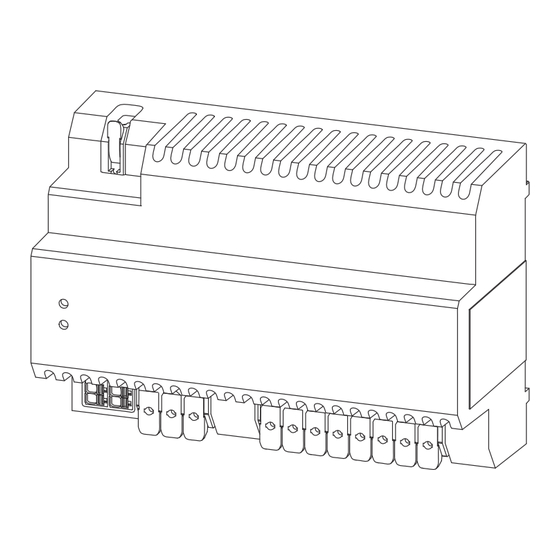
Page 37: Dimensions - Fronius Backup Controller 3P-35A
Dimensions - Fronius Backup Controller 3P-35A Fronius Backup Controller 3P‑35A...
Need help?
Do you have a question about the 3P-35A and is the answer not in the manual?
Questions and answers