
Related Manuals for Fronius Robacta TC 1000


Summary of Contents for Fronius Robacta TC 1000
- Page 1 Operating Instructions Robacta TC 1000 Robacta TC 1000 ext. Operating Instructions 42,0426,0141,EN 017-31012023...
-
Page 3: Table Of Contents
Functional principle Scope of supply and options General Robacta TC 1000 scope of supply Robacta TC 1000 options Robacta TC 1000 ext. scope of supply Robacta TC 1000 ext. options Transport Transport devices Transport notices on the packaging Controls, connections and mechanical components... - Page 4 Mains connection Bolting the Robacta TC 1000 to the underlying surface (foundation) Bolting the Robacta TC 1000 together with installation stand to the underlying surface (foundation) Screw the base unit and cleaning unit to the underlying surface (foundation) and connect...
- Page 5 Clean suction filter in parting agent container Disposal Technical data Technical data General Robacta TC 1000 / Robacta TC 1000 ext. (Base unit) / Robacta TC 1000 Twin / Robacta TC 1000 Twin Compact Cleaning unit S/P Robot control supply Digital inputs...
-
Page 6: Safety Rules
Safety rules Explanation of DANGER! safety notices Indicates immediate danger. ▶ If not avoided, death or serious injury will result. WARNING! Indicates a potentially hazardous situation. ▶ If not avoided, death or serious injury may result. CAUTION! Indicates a situation where damage or injury could occur. ▶... -
Page 7: Proper Use
Proper use The device is to be used exclusively for its intended purpose. The device is intended solely for the electromagnetic cleaning of Fronius welding torches. Any use above and beyond this purpose is deemed improper. The manufacturer shall not be held liable for any damage arising from such usage. -
Page 8: Specific Hazards
Specific hazards Stay out of the working area of the robot. The device must be incorporated into a higher-level safety system within a se- cured area. If this area has to be accessed when setup and maintenance work is carried out, make sure that the entire system is switched off for the duration of the work in this area and that it is prevented from starting up accidentally, e.g., as the result of a... -
Page 9: Risks From Mains Current And Operating Current
Protective clothing refers to a variety of different items. Operators should: Protect eyes and face from UV rays, heat and sparks using a protective visor and regulation filter Wear regulation protective goggles with side protection behind the protect- ive visor Wear stout footwear that provides insulation even in wet conditions Protect the hands with suitable gloves (electrically insulated and providing protection against heat) -
Page 10: Emc Device Classifications
The housing screws provide an adequate ground conductor connection for earth- ing the housing. The screws must never be replaced with different screws unless a reliable ground conductor connection is set up. EMC Device Devices in emission class A: Classifications Are only designed for use in industrial settings Can cause line-bound and radiated interference in other areas Devices in emission class B:... -
Page 11: Safety Measures In Normal Operation
When setting up the Robacta TC and cleaning unit, ensure an all-round clearance of at least 0.5 m (19.69 in.) from any surrounding objects, e.g. walls, other devices or objects. The Robacta TC and the cleaning unit must be set up at least 1 m (40 in.) away from computers, control lines and the welding process. -
Page 12: Safety Inspection
(e.g. relevant product standards of the EN 60 974 series). Fronius International GmbH hereby declares that the device is compliant with Directive 2014/53/EU. The full text on the EU Declaration of Conformity can be found at the following address: http://www.fronius.com Devices marked with the CSA test mark satisfy the requirements of the relevant standards for Canada and the USA. - Page 13 takes that you have found in the instructions, we will be most grateful for your comments.
-
Page 15: General
General... -
Page 17: General
The components of the Robacta TC 1000 ext. are divided between two devices: ▶ Robacta TC 1000 ext. base unit ▶ Cleaning unit S. / cleaning unit P. Robacta TC 1000 ext. (Base unit with cleaning unit S.) Recommended for vertical torch cleaning... -
Page 18: Application Areas
Robacta TC 1000 ext. (Base unit with cleaning unit P.) Recommended for horizontal torch cleaning All variants are also available in Twin and Twin Compact versions. Application The cleaning device cleans welding torches in automated steel applications. It areas has been designed for use in the... - Page 19 Type: Robacta TC 1000 Art.No.: A-4600 Wels Ser.No.: www.fronius.com EN 50 178 / EN 61000-6-2/4 IP 21 230 V 24 V control 40 sec. cycle 50-60 Hz WARNING! Risk of serious injury from: the magnetic field surrounding the cleaning opening...
-
Page 20: Parting Agent Types And Their Use
Forbidden for anyone wearing a pacemaker. people wearing a pace- maker must consult their doctor before working with the device or entering its immediate vicinity Parting agent NOTE! types and their Parting agents are not included in the scope of supply. Parting agent types and their use: "Robacta TC Cool +"... -
Page 21: Functional Principle
Device connected to the mains and the robot control ▶ The Quick Stop signal has been set ▶ Robacta TC 1000 ext. ▶ Base unit connected to the mains and the robot control ▶ Cleaning unit interconnecting hosepack connected to the base unit ▶... - Page 22 Quick Stop Ready 45 s Cleaning Start Diagram of the program sequence (1) - (4) minimal cleaning interval (5) - (7) cleaning interval...
-
Page 23: Scope Of Supply And Options
Robacta TC Robacta TC 1000 with dipping bowl and integral cleaning unit 1000 scope of Standard I/O connecting plug (X1) without cable... -
Page 24: Transport
Transport Transport The device is to be transported by the following devices: devices On pallets using a forklift truck On pallets using a lift truck Manual WARNING! Danger from machines and objects falling. This can result in serious injury and damage to property. ▶... -
Page 25: Controls, Connections And Mechanical Components
Controls, connections and mechan- ical components... -
Page 27: Safety
Safety Safety Observe the following safety rules for all work described in the "Control ele- ments, connections and mechanical components" section. WARNING! Danger due to incorrect operation and incorrectly performed work. This can result in serious injury and damage to property. ▶... -
Page 28: Control Panel
Control panel General All functions of the cleaning unit are activated by the robot control. For adjust- ment, the cleaning operation can be manually triggered on the control panel. NOTE! The individual illustrations may differ slightly from your device. However, the functioning of the controls and the connections is identical. Control panel Mains voltage indicator lights up when the device is powered by mains voltage... - Page 29 if the fill level in the dipping bowl drops below minimum if the dipping bowl is not used, hence there is no parting agent in the dipping bowl NOTE! If the dipping bowl is used, it should be refilled with parting agent as soon as the fill level indicator lights up.
-
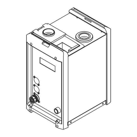
Page 30: Robacta Tc 1000
Robacta TC 1000 Robacta TC 1000 connec- tions and mech- (13) anical compon- ents (12) (10) (11) Front of device Rear of device Level sensor monitors the parting agent fill level in the dipping bowl Blanking cover Standard I/O connection socket (X1) - Page 31 (10) Parting agent nebuliser connection for connecting to the parting agent nebuliser; to supply the parting agent nebuliser with compressed air (11) Spray device connection for connecting to the parting agent nebuliser; for spraying the com- pressed air/parting agent mixture into the cleaning opening If a parting agent nebuliser is not used, connect parting agent nebuliser connection (10) to spray device connection (11).
-
Page 32: Base Unit And Cleaning Unit
Base unit and cleaning unit P. Base unit and cleaning unit P. (10) Spatter tray for welding residues Cleaning unit P. Spray device connection for connecting to the parting agent nebuliser; for spraying the com- pressed air/parting agent mixture into the cleaning opening If a parting agent nebuliser is not used, connect parting agent nebuliser connection (5) to spray device connection (3). - Page 33 NOTE! To avoid excess soiling, only use the device with the brush seal in place. Wire cutter connection socket for electrically controlling the wire cutter Interconnecting hosepack with strain-relief device WARNING! Risk of serious injury and damage from electric shock. Once the ready-to-clean indicator lights up, the interconnecting hosepack must not be disconnected from the base unit.
-
Page 34: Base Unit And Cleaning Unit
Base unit and cleaning unit S. Base unit and cleaning unit S. (11) (10) Cleaning unit S. Cleaning opening with internal parting-agent injection nozzle and brush seal for cleaning the gas nozzle and the inside of the welding torch for coating the gas nozzle and welding torch interior with parting agent NOTE! To avoid excess soiling, only use the device with the brush seal in place. - Page 35 Parting agent nebuliser connection for connecting to the parting agent nebuliser; to supply the parting agent nebuliser with compressed air Interconnecting hosepack with strain-relief device WARNING! Risk of serious injury and damage from electric shock. Once the ready-to-clean indicator lights up, the interconnecting hosepack must not be disconnected from the base unit.
-
Page 36: Standard I/O Connecting Plug (X1) Pin Assignment For Robot Control
Standard I/O connecting plug (X1) pin assign- ment for robot control General WARNING! Danger from electric current. This can result in serious personal injury and damage to property. ▶ The cleaning device must remain de-energised until the installation is fully complete. - Page 37 Roboter +24 V +24 V +24 V HIGH - Quick Stop LOW - Quick Stop +24 V HIGH - Cleaning Start LOW - Cleaning Start +24 V Supply Voltage max. 20 mA Ready +24 V Supply Voltage max. 20 mA Fluid Level Control Supply Voltage +24 V...
-
Page 39: Installation And Commissioning
Installation and commissioning... -
Page 41: Safety
This can result in serious personal injury and damage to property. ▶ All the work and functions described in this document must only be carried out by a trained Fronius service technician. ▶ Read and understand this document in full. -
Page 42: Before Commissioning
Before commissioning Operators, main- WARNING! tenance person- Risk of machines starting automatically. This can result in serious injury and damage to property. ▶ The device must only be operated/serviced by 1 person at a time. ▶ Ensure that there is only 1 person within the working area of the device when the device is being worked on. - Page 43 CAUTION! Risk of serious damage as the result of incorrect mains voltage. If the mains voltage lies outside the tolerances given in the technical data, do not under any circumstances connect the device directly to the mains. In this case, the device may only be operated using the optional auto-transformer.
-
Page 44: Bolting The Robacta Tc 1000 To The Underlying Surface (Foundation)
Bolting the Robacta TC 1000 to the underlying surface (foundation) Bolting the WARNING! Robacta TC 1000 together Danger from machines toppling over or falling. with installation This can result in serious personal injury and damage to property. ▶ stand to the un-... -
Page 45: Screw The Base Unit And Cleaning Unit To The Underlying Surface (Foundation) And Connect
Screw the base unit and cleaning unit to the un- derlying surface (foundation) and connect them to each other Installation in- NOTE! structions Before installing the base unit and the cleaning unit, ensure that the cleaning unit interconnecting hosepack is long enough for the intended installation posi- tions. - Page 46 WARNING! Danger from electrical current. This can result in serious personal injury and damage to property. ▶ If the interconnecting hosepack needs to be disconnected after the base unit has been started up, carry out the following steps before disconnecting the interconnecting hosepack: ▶...
- Page 47 WARNING! Danger from electrical current. This can result in serious personal injury and damage to property. ▶ If the interconnecting hosepack needs to be disconnected after the base unit has been started up, carry out the following steps before disconnecting the interconnecting hosepack: ▶...
-
Page 48: Installing The Wire Cutter
Installing the wire cutter Installing the Attach the wire cutter holder (1) to wire cutter on the cleaning device the Robacta TC Fix the wire cutter (2) to the holder 1000 (1) using the two screws, two wash- ers, two lock washers and two nuts as shown. -
Page 49: Fitting The Wire Cutter To Cleaning Unit P
Fitting the wire Screw the wire cutter (1) to the cutter to clean- cleaning unit (2) using 2 screws, 2 ing unit P washers, 2 lock washers and 2 nuts as shown. The installer is respons- ible for selecting the right screws, washers, lock washers and nuts If using an electrically controlled wire cutter: Plug the wire cutter... -
Page 50: How The Electrically-Controlled Wire Cutter Works
How the elec- The electrically-controlled wire cutter opens and closes when there is an active trically-con- signal from the robot control. trolled wire cut- ter works... -
Page 51: Filling The Dipping Bowl With Parting Agent
Filling the dipping bowl with parting agent Filling the dip- NOTE! ping bowl with Only use the "Robacta TC Cool +" parting agent supplied by the manufacturer. parting agent The composition of the manufacturer's parting agent is intended specifically for the Robacta TC. -
Page 52: Installing And Commissioning The Parting Agent Nebuliser (Only For Robacta Tc 1000)
Installing and commissioning the parting agent nebuliser (only for Robacta TC 1000) Installing the NOTE! parting agent nebuliser on the If the parting agent nebuliser is positioned too high, there is a risk of parting Robacta TC agent leaking out around the spray holes in the cleaning opening. -
Page 53: Starting Up The Parting Agent Nebuliser
Starting up the NOTE! parting agent nebuliser Only use "Robacta Reamer" parting agent supplied by the manufacturer. The composition of the manufacturer's parting agent is intended specifically for the Robacta TC. If other manufacturers' products are used, trouble-free opera- tion cannot be guaranteed. Open the sealing plug (1) Fill with "Robacta Reamer"... - Page 54 Starting up the parting agent nebuliser V Robacta TC NOTE! 1000: Installing parting agent If the parting agent nebuliser is positioned too high, there is a risk of parting agent leaking out around the spray holes in the cleaning opening. Position the nebuliser V parting agent nebuliser below the upper edge of the housing.
- Page 55 NOTE! Ensure that the length of the parting agent hose between the device and the parting agent nebuliser does not exceed 1 m (40 in.). Screw the parting agent nebuliser (1) to the cleaning unit (2) installation stand using 2 screws, 2 washers, 2 lock washers and 2 nuts as shown. The in- staller is responsible for selecting the right screws, washers, lock washers and nuts NOTE!
-
Page 56: Filling The "Robacta Reamer" Parting Agent Container With Parting Agent
Bolt the parting agent nebuliser (1) to a level, firm and vibration-free surface close to the cleaning device (2). The installer is responsible for selecting the installation location and the right fixings NOTE! Use the parting agent hoses supplied with the parting agent nebuliser to con- nect the nebuliser to the cleaning unit. -
Page 57: Connecting The 'Robacta Reamer' Parting Agent Container (10 Litres) To The Cleaning
Connecting the Remove the existing 'Robacta Reamer' parting agent container (2) from the 'Robacta Ream- container housing er' parting agent Disconnect the parting agent hose (1) from connection Y in the container container (10 housing litres) to the cleaning device Prepare the 10-litre "Robacta Reamer"... - Page 58 Connect the parting agent hose (3) to connection Y in the container housing...
-
Page 59: Fitting And Using The Fill-Level Control Sensor
Fitting and using the fill-level control sensor General NOTE! The fill-level control sensor can only be used in conjunction with parting agent nebuliser V. Controls and in- 'OUT OFF' button dicators on the for programming the sensor sensor 'OUT ON' button for programming the sensor indicates the sensor operating status... -
Page 60: Fitting The Fill-Level Control Sensor
Fitting the fill- NOTE! level control First press the upper part of the sensor sensor into the installation adapter as shown - the sockets (1) on the installa- tion adapter must fit into the recesses (2) in the sensor. When the upper part of the sensor is properly lined up in the installation ad- apter, press the sensor fully into the installation adapter - the latch (3) on... -
Page 61: Calibrating The Empty State
Calibrating the Drain the parting agent container empty state until the parting agent level is at least 20 mm (0.787 in.) below the sensor Establish a power supply to the sensor 20 mm (0.79 in.) Press the "OUT OFF" button for between 2 and 6 seconds The LED on the sensor flashes slowly... -
Page 62: Locking/Unlocking The Fill-Level Control Sensor
Locking/unlock- NOTE! ing the fill-level It is possible to lock the fill-level con- control sensor trol sensor to prevent it from being adjusted accidentally. 10 s 10 s Locking the fill-level control sensor: Simultaneously press the "OUT OFF" and "OUT ON" buttons for at least 10 seconds The LED status changes briefly if the LED lights up when locking, it will go out briefly after locking... -
Page 63: Starting Up The Cleaning Device
Cleaning device is bolted to underlying surface (foundation) Cleaning device connected to mains Cleaning device is connected to the robot control The following requirements must be met before the Robacta TC 1000 ext. is star- ted up: The base unit is screwed to the underlying surface... - Page 64 NOTE! Ensure that the gas nozzle does not touch the housing components of the clean- ing opening at any time.
-
Page 65: Cleaning Programme
Cleaning programme Overview of pro- Welding gram sequence Cooling torch in dipping bowl with dipping Cleaning gas nozzle tip bowl Welding Cooling torch in dipping bowl Cleaning the nozzle fitting Welding Overview of pro- Welding gram sequence Cleaning gas nozzle tip with parting Spraying in parting agent agent nebuliser... -
Page 66: Cleaning The Gas Nozzle Tip - Detailed Description
Depending on the application, hold the welding torch in the dipping bowl for approximately 1 - 4 seconds so that any air in the torch can escape and the torch can cool sufficiently Raise the welding torch back to its original position above the dipping bowl Allow the welding torch to drip for approximately 1 - 4 seconds or blow down it with compressed air using the hosepack before bringing it back to its ori- ginal position for cleaning... -
Page 67: Spraying Parting Agent - Detailed Description
Position the welding torch approx. 40 mm (1.57 in.) centrally above the middle of the cleaning opening NOTE! If the brush seal (1) is not fitted, note 15 mm the changed reference point when po- (0.59 in.) sitioning the welding torch. 25 mm (0.98 in.) Insert welding torch vertically into... -
Page 68: Cleaning Program Sequence With Dipping Bowl
Ensure that not too much parting agent has accumulated on the gas nozzle (no droplet formation). If this is the case: Reduce the spray time or After the cleaning operation, blow out the welding torch with com- pressed air using the hosepack Cleaning pro- Start "Welding torch gram sequence... -
Page 69: Cleaning Program Sequence With Parting Agent Nebuliser
Cleaning pro- Set 1/Reset 1 Start "Welding torch gram sequence Blow compressed air through torch cleaning" program with parting agent nebuliser Set 2/Reset 2 "Start cleaning" signal Move to position C Set 3/Reset 3 "Spray parting agent" signal Marker query 0 or 1 if marker = 1 if marker = 0... -
Page 71: Troubleshooting, Maintenance And Disposal
Troubleshooting, maintenance and disposal... -
Page 73: Safety
This can result in serious personal injury and damage to property. ▶ All the work and functions described in this document must only be carried out by a trained Fronius service technician. ▶ Read and understand this document in full. - Page 74 WARNING! Danger from inadequate ground conductor connection. This can result in serious personal injury and damage to property. ▶ The housing screws provide a suitable ground conductor connection for earthing the housing and must NOT be replaced by any other screws which do not provide a reliable ground conductor connection.
-
Page 75: Troubleshooting
Troubleshooting Troubleshooting Mains voltage indicator not lit Mains cable connected Cause: Faulty mains cable Remedy: Check mains cable Ready-to-clean signal not transmitted to robot control Mains voltage indicator lit Cause: Quick Stop is active (HI - Quick Stop = LO / LO - Quick Stop = HI) Remedy: Deactivate Quick Stop (HI - Quick Stop = HI / LO - Quick Stop = LO) Cause:... - Page 76 Cause: The "Robacta Reamer" parting agent container is empty Remedy: Fill with parting agent Cause: Interconnecting hosepack damaged (only on Robacta TC 1000 ext.) Remedy: Contact After-Sales Service Pores in the weld seam Cause: Too much parting agent inside the welding torch Remedy: Remove parting agent residue by blowing out the torch interior.
- Page 77 Error is sent to the robot. Overtemperature and fill level indicators flash at the same time, no cleaning takes place Cause: Quick Stop is active (HI - Quick Stop = LO / LO - Quick Stop =HI) Remedy: Deactivate Quick Stop (HI - Quick Stop = HI / LO - Quick Stop =LO) Cause: Fault in the cleaning device Remedy:...
-
Page 78: Fault Procedure For Robacta Tc 1000 Ext
Fault procedure for Robacta TC 1000 ext. Fault procedure WARNING! Risk of serious injury and material damage from electric shocks. The cleaning device has a serious fault ▶ the overtemperature (1) and fill level (2) indicators are flashing at the same time ▶... -
Page 79: Care, Maintenance And Disposal
Check the condition of the brush seal above the cleaning opening. Replace the brush seal if worn Robacta TC 1000 ext.: Empty the spatter tray for welding residues on the cleaning unit S. Clean the inside of the cleaning unit cleaning opening... -
Page 80: Every 3 Months
Every 6 months NOTE! Do not bring the air nozzle too close to electronic parts. Robacta TC 1000 / Robacta TC 1000 ext. Open (base unit and cleaning unit) and blow clean using dry reduced compressed air Every 12 months... -
Page 81: Disposal
10 litre container: Disposal Dispose of in accordance with the applicable national and local regulations. -
Page 83: Technical Data
Technical data... -
Page 85: Technical Data
▶ Dimension the mains lead and its fuse to suit the device being used. The technical data shown on the rating plate applies. Robacta TC Robacta TC 1000 / 1000 / Robacta Twin / Twin Com- Robacta TC 1000 TC 1000 ext. -
Page 86: Robot Control Supply
Cleaning unit S Cleaning unit P Weight (without "dip-in" parting 6 kg 8 kg agent) 13.23 Ib. 17.64 lb. NOTE! Cleaning units S and P are also available for Twin and Twin Compact torch shapes. Robot control Maxim- supply Condition Minimum Typical Supply voltage... - Page 87 Minimum Typical Maximum Overvoltage protection 60 V / 60 Incorrectly connected out- 60 V Invers put voltage Input resistance for open 100 kOhm Open output Input resistance for active 8 Ohm 10 Ohm 12 Ohm output Residual input voltage Output capacitance 47 nF output dU /...
Need help?
Do you have a question about the Robacta TC 1000 and is the answer not in the manual?
Questions and answers