Advertisement
A
RELAX
MIST
QUALITY STEAM BATH EQUIPMENT
QUICK TOUCH TIMER
CONTROL
(PACKAGED INSIDE
ELECTRICAL BOX)
1. GENERAL INFORMATION (See Steam Generator Selecti on)
STEAM GENERATOR LOCATION
The steam generator should be located in a venti lated area
outside of, but within 20 feet of the shower or steam room,
where the steam pipes can be installed without the possibility
of a steam trap. The steam generator may be placed under the
fl oor, in a closet, or any convenient locati on where it WILL BE
LEVEL, DRY, AND WILL NOT FREEZE in the winter. The steam
generator MUST be easily accessible should service be required
in the future. INSTALL THE STEAM GENERATOR WITH THE COPPER
STEAM PIPES COMING OUT OF THE TOP OF THE APPLIANCE
AND THE ELECTRICAL BOX FACING THE ACCESS! See Fig. 1.
RELAX
A
MIST
®
QUALITY STEAM BATH EQUIPMENT
STEAM PIPING AND STEAM NOZZLE
(To and in the steam room)
The steam pipes must be a minimum of 1/2 inch I.D. rigid copper.
Installing the steam pipes using the most direct or shortest route
(WITHOUT FORMING A STEAM TRAP) and with the fewest number
of elbows will, in most cases, maintain a lower pressure (less than
1 lb) in the boiling tank than a longer route with many elbows.
1-800-Y-U-STEAM
(1-800-987-8326)
INSTALLATION INSTRUCTIONS
®
JR-3 OR JR-4 STEAM GENERATOR
USE ONLY RELAX-A-MIST® FACTORY SUPPLIED PARTS
A
RELAX
MIST
®
QUALITY STEAM BATH EQUIPMENT
A
RELAX
MIST
®
QUALITY STEAM BATH EQUIPMENT
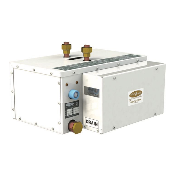
Fig. 1
MODELS JR-3 & JR-4
240/208 VOLTS 1 PHASE
CONTROL
CORD SET
WATER
INLET
The Relax-A-Mist® steam nozzle installati on uses standard
constructi on materials, tools and methods. Depending on wall
thickness, custom sized nipples may need to be fabricated by the
plumber or purchased from a local hardware store. It is important
to install the steam nozzles in an area where a person cannot
be burned from the hot steam exiti ng the nozzles. The steam
nozzles were designed to be installed on a fl at surface. During
the fi nal installati on, the steam nozzles supplied MUST be used.
See Steam Piping to Bath or Shower, CAUTION 1-3, and Fig. 2.
UNION 1/2"
DRAIN
CAUTION: There is to be NO RESTRICTION in the STEAM
PIPES BETWEEN the STEAM GENERATOR and the STEAM
NOZZLES that would in any way cause PRESSURE to
build in the STEAM GENERATOR. INSTALL the STEAM
NOZZLES 12 INCHES above the fi nished fl oor, in a
LOCATION where the STEAM WILL NOT BURN anyone.
TIMER SWITCH (Steam Generator Control)
The Quick Touch Timer can be located inside or outside the steam
room. If using the opti onal Time and Temperature Control, refer
to that control's installati on instructi ons now. Relax-A-Mist®
ti mer switches are not precision ti ming devices. See CAUTION 11.
DRAIN VALVE OPTION (Ask Dealer For Details)
A 3/4 inch copper, female adapter (located below the water
supply connecti on), can be plumbed to a drain with either
a manual shut-off or an automati c drain valve installed at
the steam generator (purchased separately). See Fig. 2.
1
CN
2015
LR 42682-8
TWO 1/2" STEAM NOZZLE TD*
AND ESCUTCHEON
* Tear Drop Essenti al Oil Reservoir
STEAM LINE 1/2"
Fig. 2
www.relax-a-mist.com
Advertisement
Table of Contents

Related Manuals for RELAX-A-MIST JR-3


Summary of Contents for RELAX-A-MIST JR-3
- Page 1 The Quick Touch Timer can be located inside or outside the steam Fig. 1 room. If using the opti onal Time and Temperature Control, refer to that control’s installati on instructi ons now. Relax-A-Mist® ti mer switches are not precision ti ming devices. See CAUTION 11. STEAM PIPING AND STEAM NOZZLE...
- Page 2 INSTALLATION INSTRUCTIONS - JR-3 & JR-4 ELECTRICAL SUPPLY & PIPING 2. ROUGH-IN and ground, of adequate gauge to carry the WATER SUPPLY (According to Local Plumbing Code) necessary amperage from the fuse or circuit The water supply pipe should be equipped with a shut-off that...
-
Page 3: Final Installation
Relax-A-Mist® wires inside the electrical box. See Fig. 6. Care MUST be taken to AVOID A STEAM TRAP! Water On the side panel of the steam generator electrical must be able to drain from all secti ons of the steam box, remove the protecti ve label marked “Remove To... - Page 4 INSTALLATION INSTRUCTIONS - JR-3 & JR-4 FINAL STEAM PIPE INSTALLATION ii) When the display illuminates the horizontal bars, press STEAM PIPING the “on/off” button; the display will show 30 minutes. THE STEAM GENERATOR MUST BE POSITIONED WITH THE Listen to hear the generator filling with water and the STEAM PIPES COMING OUT OF THE TOP OF THE UNIT.
-
Page 5: Start-Up Instructions
Caution: The steam nozzles are HOT. Warning: HOT Steam will burn you. 6. Within approximately 2 minutes from energizing the Relax-A-Mist®, steam will be entering the steam room. Scalding Caution: When the generator is first turned on, there may be an initial burst of hot water from the steam nozzles until the steam lines have come up to temperature. - Page 6 INSTALLATION INSTRUCTIONS - JR-3 & JR-4 DIAGRAM SHEET JR-3 & JR-4 DIAGRAM SHEET RELAX MIST 2015 JR-3 & JR-4 - PLUMBING ® QUALITY STEAM BATH EQUIPMENT WATER SUPPLY TWO 1/2” HOSE CONNECTION FOR WATER SUPPLY STEAM PIPES (FACTORY SUPPLIED) ***DO NOT INSTALL FLOW STABILIZER UNTIL AFTER...
-
Page 7: Modular Connectors
INSTALLATION INSTRUCTIONS - JR-3 & JR-4 DIAGRAM SHEET JR-3 & JR-4 DIAGRAM SHEET RELAX MIST 2015 JR-3 & JR-4 - ELECTRICAL ® QUALITY STEAM BATH EQUIPMENT POWER SUPPLY 240/208V 1Ph ELECTRICAL BOX MUST BE ACCESSIBLE • CONNECT GROUND WIRE TO GROUNDING LUG •... -
Page 8: Warranty Policy
There is no cosmetic warranty on installed parts or controls. Any Relax-A-Mist® products containing defective parts, if returned prepaid to an authorized Service Depot within the one year or 18 month time limit, will be repaired free of charge, F.O.B. the authorized Service Depot making such repairs.
Need help?
Do you have a question about the JR-3 and is the answer not in the manual?
Questions and answers