Advertisement
A
RELAX
MIST
QUALITY STEAM BATH EQUIPMENT
QUICK TOUCH TIMER
CONTROL
(PACKAGED INSIDE
ELECTRICAL BOX)
1. GENERAL INFORMATION (See Steam Generator Selection)
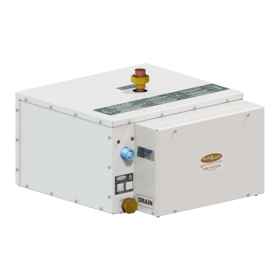
STEAM GENERATOR LOCATION
The steam generator should be located in a ventilated area
outside of, but within 20 feet of the shower or steam room,
where the steam pipe can be installed without the possibility of a
steam trap. The steam generator may be placed under the floor,
in a closet, or any convenient location where it WILL BE LEVEL,
DRY, AND WILL NOT FREEZE in the winter. The steam generator
MUST be easily accessible should service be required in the
future. INSTALL THE STEAM GENERATOR WITH THE COPPER
STEAM PIPE COMING OUT OF THE TOP OF THE APPLIANCE
AND THE ELECTRICAL BOX FACING THE ACCESS! See Fig. 1.
A
RELAX
MIST
®
QUALITY STEAM BATH EQUIPMENT
STEAM PIPING AND STEAM DIFFUSER
(To and in the steam room)
The steam pipe must be a minimum of 1 inch I.D. rigid copper
and must be manifolded to two 3/4 inch pipes at the steam
generator OR at the area to be steamed. Installing the steam
pipe using the most direct or shortest route (WITHOUT
FORMING A STEAM TRAP) and with the fewest number of
elbows will, in most cases, maintain a lower pressure (less than
1-800-Y-U-STEAM
(1-800-987-8326)
INSTALLATION INSTRUCTIONS
®
CR-12 OR CR-14 STEAM GENERATOR
USE ONLY RELAX-A-MIST® FACTORY SUPPLIED PARTS
RELAX
A
MIST
®
QUALITY STEAM BATH EQUIPMENT
A
RELAX
MIST
®
QUALITY STEAM BATH EQUIPMENT
Fig. 1
MODELS CR-12 & CR-14
208 VOLTS 3 PHASE
CONTROL
CORD SET
WATER
INLET
1 lb) in the boiling tank than a longer route with many elbows.
The Relax-A-Mist® steam diffusers use standard construction
materials, tools and methods. Depending on wall thickness,
custom sized nipples may need to be fabricated by the plumber
or purchased from a local hardware store. It is important to
install the steam diffusers in an area where a person cannot
be burned from the hot steam exiting the diffusers. The steam
diffusers were designed to be installed on a flat surface. During
the final installation, the steam diffusers supplied MUST be used.
See Steam Piping to Bath or Shower, CAUTION 1-3, and Fig. 2.
STEAM LINE 3/4"
TEE 1" TO 3/4"
UNION 1"
DRAIN
Option #1
CAUTION: There is to be NO RESTRICTION in the STEAM
PIPE BETWEEN the STEAM GENERATOR and the STEAM
DIFFUSERS that would in any way cause PRESSURE to
build in the STEAM GENERATOR. INSTALL the STEAM
DIFFUSERS 12 INCHES above the finished floor, in a
LOCATION where the STEAM WILL NOT BURN anyone.
TIMER SWITCH (Steam Generator Control)
The Quick Touch Timer can be located inside or outside the steam
room. If using the optional Time and Temperature Control, refer
to that control's installation instructions now. Relax-A-Mist®
timer switches are not precision timing devices. See CAUTION 11.
DRAIN VALVE OPTION (Ask Dealer For Details)
A 3/4 inch copper, female adapter (located below the water
supply connection), can be plumbed to a drain with either
a manual shut-off or an automatic drain valve installed at
the steam generator (purchased separately). See Fig. 2.
1
CN
2016
TWO 3/4" STEAM DIFFUSERS
STEAM LINE 1"
TEE 1" TO 3/4"
UNION 1"
DRAIN
STEAM
LINE 3/4"
Option #2
Fig. 2
www.relax-a-mist.com
Advertisement
Table of Contents

Related Manuals for RELAX-A-MIST CR-12


Summary of Contents for RELAX-A-MIST CR-12
- Page 1 QUICK TOUCH TIMER CONTROL TWO 3/4” STEAM DIFFUSERS WATER (PACKAGED INSIDE CR-12 OR CR-14 STEAM GENERATOR ELECTRICAL BOX) INLET USE ONLY RELAX-A-MIST® FACTORY SUPPLIED PARTS 1. GENERAL INFORMATION (See Steam Generator Selection) 1 lb) in the boiling tank than a longer route with many elbows.
- Page 2 INSTALLATION INSTRUCTIONS - CR-12 & CR-14, 3PH ELECTRICAL SUPPLY & PIPING 2. ROUGH-IN location. Leave sufficient length at each end of WATER SUPPLY (According to Local Plumbing Code) cord set for the final installation connections. The water supply pipe should be equipped with a shut-off that See CAUTION 8-10.
-
Page 3: Final Installation
INSTALLATION INSTRUCTIONS - CR-12 & CR-14, 3PH FINAL INSTALLATION floor and in a location away from the user’s pathways, ELECTRICAL (According to Local Electrical Code) where steam will burn anyone, preferably Check to ensure that the supply voltage (208V 3 Phase) is on the same wall as the shower controls. - Page 4 INSTALLATION INSTRUCTIONS - CR-12 & CR-14, 3PH FINAL STEAM PIPE INSTALLATION ii) When the display illuminates the horizontal bars, press elbow, past your original mark. This is the length of brass nipple the “on/off” button; the display will show 30 minutes.
-
Page 5: Start-Up Instructions
INSTALLATION INSTRUCTIONS - CR-12 & CR-14, 3PH STARTUP INSTRUCTIONS Relax-A-Mist® Steam Generator Start Up The following instructions are for the Quick Touch Timer. If you have installed the Time & Temperature Control with remote or an alternate control, refer to their start up instructions now. - Page 6 INSTALLATION INSTRUCTIONS - CR-12 & CR-14, 3PH DIAGRAM SHEET CR-12 & CR-14 DIAGRAM SHEET RELAX MIST 2016 CR-12 & CR-14 3Ph - PLUMBING ® QUALITY STEAM BATH EQUIPMENT WATER SUPPLY ONE 1” HOSE CONNECTION FOR WATER SUPPLY STEAM PIPE (FACTORY SUPPLIED)
-
Page 7: Modular Connectors
INSTALLATION INSTRUCTIONS - CR-12 & CR-14, 3PH DIAGRAM SHEET CR-12 & CR-14 DIAGRAM SHEET RELAX MIST 2016 CR-12 & CR-14 3Ph - ELECTRICAL ® QUALITY STEAM BATH EQUIPMENT POWER SUPPLY 208V 3Ph ELECTRICAL BOX MUST BE ACCESSIBLE • CONNECT GROUND WIRE TO GROUNDING LUG •... -
Page 8: Warranty Policy
INSTALLATION INSTRUCTIONS - CR-12 & CR-14, 3PH WARRANTY POLICY RELAX MIST ® QUALITY STEAM BATH EQUIPMENT WARRANTY POLICY For a period of one year from the date of installation, or 18 months from the date of manufacture, whichever comes first, all parts and assemblies are warranted as to workmanship and materials used in their manufacture.
Need help?
Do you have a question about the CR-12 and is the answer not in the manual?
Questions and answers