
Related Manuals for Siemens AC5102


Summary of Contents for Siemens AC5102
- Page 1 Advanced Central Controller AC5102 Technical Manual Rev 5.0 Siemens AB Security Products...
- Page 2 Data and design subject to change without notice. / Supply subject to availability. © 2014 Copyright by Siemens AB English We reserve all rights in this document and in the subject thereof. By acceptance of the document the recipient acknowledges these rights and undertakes not to publish the document nor the subject thereof in full or in part, nor to make them available to any third party without our prior express written authorization, nor to use it for any purpose other than for which it was delivered to him.
-
Page 3: Table Of Contents
Content 1 About this document 2 Scope of Delivery 3 Details for Ordering 4 General Safety Precautions 5 Standards and Guidelines 5.1 EU Directives 5.2 FCC 5.3 UL-Directives 6 Technical Specifications 6.1 Dimensions 6.2 Interfaces 6.3 Indicators (LEDs) 7 Installation 8 Hardware Connections 8.1 FLN Connectivity Options 8.2 Bus Termination of the FLNs... -
Page 4: About This Document
Contacting us If you have technical questions regarding the product, please contact our Technical Competence Center. Hotline Europe Phone +49 89 9221 8000 Email: sp.support.de@siemens.com Hotline South & North America Phone: +1 800 877 7545 Email: sipasssupport@internal.siemens.com Hotline Asia Phone: +86 10 6296 0119... -
Page 5: Scope Of Delivery
2 Scope of Delivery 2 Scope of Delivery 1 x AC5102 Advanced Central Controller 7 x 6-Position connector 1 x 3-Position connector 1 x Installation manual Siemens AB 2014-03-12 Security Products... -
Page 6: Details For Ordering
3 Details for Ordering 3 Details for Ordering Type Part no. Designation Weight AC5102 S54507-C22-A1 Advanced central controller (ACC) 990 g Accessories, not included in scope of delivery! ACK5110 6FL7820-8FB11 SiPass integrated modem cable 200 g Siemens AB 2014-03-12 Security Products... -
Page 7: General Safety Precautions
Connect the cable shielding to all connection points. Ground cable shielding only on one side. The precautions applicable for CMOS technology are to be applied to activities involving server circuit boards and soldering. Never install a live circuit board. Siemens AB 2014-03-12 Security Products... -
Page 8: Standards And Guidelines
This product complies with the requirements of the European Directives 89/336/EEC “Directive of Electromagnetic Compatibility” and 2006/95/EEC “Low Voltage Dir- ective”. The EU declaration of conformity is available from Siemens AB, Infrastructure & Cities Security Products Englundavägen 7 SE-171 24 Solna, Sweden European Directive 2004/108/EC „Electromagnetic Com-... -
Page 9: Ul-Directives
If the unit is wired for fail secure operation, it must be used in conjunction with UL Lis- ted panic hardware. The unit shall not impair the intended operation of panic hardware used in conjunction with it. Siemens AB 2014-03-12 Security Products... -
Page 10: Technical Specifications
Grey and blue Storage temperature -30 to +65 °C (-22 to 149 °F) Humidity 5 – 93% (non condensing) Dimensions (W x H x D) 124 x 220 x 54 mm Approval CE, UL294, C-Tick, FCC Siemens AB 2014-03-12 Security Products... -
Page 11: Dimensions
6 Technical Specifications 6.1 Dimensions Note that the unit is recommended to be mounted in upright position to achieve the best ventilation. Siemens AB 2014-03-12 Security Products... -
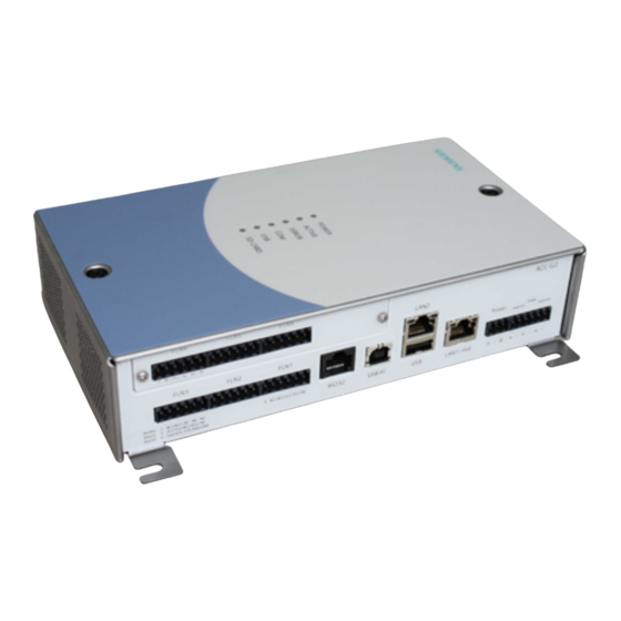
Page 12: Interfaces
Input for the connection of a tamper switch, used to monitor the Tamper status of the cabinet door Optical relay (max. 12 V, 100 mA) used to connect an alarm out- Alarm out put device such as a siren / buzzer / strobe light. Siemens AB 2014-03-12 Security Products... -
Page 13: Indicators (Leds)
6.3 Indicators (LEDs) The following tables describe the operation of the LEDs located on the ACC. Front LEDs POWER On: The ACC is connected to the power supply ACTIVE Blinking: The ACC is working correctly. ERROR On: An error has occurred. Blinking: The ACC is communicating via the FLN ports On: A USB device is connected SD-CARD On: A SD-Card is inserted... -
Page 14: Installation
3. Select the appropriate drill bit according to the mounting surface / hole size and drill the holes in the locations marked (if required). 4. Fasten the ACC to the surface using screws or standoffs. 5. Connect the ACC. See "Hardware Connections" on page 16. Siemens AB 2014-03-12 Security Products... - Page 15 Mount the cover back. 7. Apply power to the ACC and test its operation. This step will require configuration of the ACC and downloading of the device database. Firmware upgrade may also be required. Siemens AB 2014-03-12 Security Products...
-
Page 16: Hardware Connections
Note: A short circuit between the two power fail input pins indicates a power failure. 6. Ensure that the ACC is correctly grounded, by connecting the ground terminal on the ACC's power port to the building earth ground. 7. Check all connections thoroughly. Siemens AB 2014-03-12 Security Products... -
Page 17: Fln Connectivity Options
8 Hardware Connections 8.1 FLN Connectivity Options The AC5102 has 6 FLNs (Field Level Network) to communicate with devices, which operates over RS485. At the 6 FLN-ports the following devices can be connected: ADS52x0 (SRI) Single Reader Interface ADD51x0 (DRI) -
Page 18: Bus Termination Of The Flns
For RS485 and RS422 functionality the following double dip switches must be closed. FLN2 FLN3 X602, X603 X600, X601 Each dip switch consists of two switches Each dip switch consists of two switches FLN 1, 4, 5 & 6 termination Siemens AB 2014-03-12 Security Products... - Page 19 8 Hardware Connections FLN 2 & 3 termination Siemens AB 2014-03-12 Security Products...
-
Page 20: Jumper Description
X600 … X603 OFF = switch open. End of line is disabled. X510 & X520 Jumper fitted = switch closed. End of line is enabled. Jjumper not fitted = switch open. End of line is disabled. Siemens AB 2014-03-12 Security Products... -
Page 21: Fln Device Load Limitations
FLN 2 16 loads FLN 3 16 loads FLN 4 16 loads FLN 5 16 loads FLN 6 16 loads Example of a Load calculation: ADE5300 + AFI5100 + 2 x ADD5100 = 16 loads Siemens AB 2014-03-12 Security Products... -
Page 22: Recommended Cable Specifications
RJ45 7 x 32 Tinned Copper Polyethylene Aluminum foil- Polyester tape Power 19 x 30 Tinned Copper Polyethylene Unshielded 8.6 Maximum Cable Length RS232 Power fail Tamper Ethernet 100 m FLN (RS485, RS422) 1200 m Siemens AB 2014-03-12 Security Products... -
Page 23: Software Configuration
9 Software Configuration 9 Software Configuration The network settings of the AC5102 Controller can be configured using a Windows application, and an appropriate USB cable. This configuration requires the USB RNDIS driver (an Ethernet-over-USB driver) to be installed. The pre-requisites required for this configuration are listed below. - Page 24 Issued by Siemens AB Industry Sector Security Products International Headquarter © 2014 Copyright by Siemens AB Englundavägen 7 Data and design subject to change without notice. SE-171 24 Solna Supply subject to availability. Tel. +46 8 629 0300 www.siemens.com/securityproducts Document Nr...
Need help?
Do you have a question about the AC5102 and is the answer not in the manual?
Questions and answers