Table of Contents

Subscribe to Our Youtube Channel
Related Manuals for Apex Digital DNP3


Summary of Contents for Apex Digital DNP3
- Page 1 DNP3 Device Manual The APEX DNP3 device is designed to comply with the regulations of PUCs (Public Utility Companies - energy utilities) which require a remote management interface for distributed renewable energy generators.
-
Page 2: Table Of Contents
DNP3 Device Table Of Contents: 1. Introduction 1.1 Device Documentation 1.2 About This Manual 2. Safety Warnings 2.1 Symbols 2.2 Purpose 2.3 Transport Damage Check 2.4 Staff 2.5 General Hazards Resulting From Non-Compliace With Safety Standards 2.6 Special Hazards 2.7 Legal And Compliance 2.8 Local Requirements... -
Page 3: Introduction
1.2 ABOUT THIS MANUAL This manual describes the correct use and features of the Apex DNP3 Device. It includes technical data as well as user instructions and specifications to provide information about its correct functioning. This document is subject to regular updates. -
Page 4: Transport Damage Check
Immediately after receiving the package, make sure that the packaging and the device have no signs of damage. If the packaging shows any sign of damage or impact, damage of the DNP3 Device should be suspected and it should not be installed. If this occurs, please contact Apex customer service. -
Page 5: Local Requirements
PCSs and is to be installed in a commercial setting. The Apex DNP3 device should only be used for this purpose. Apex is not liable for any damages caused by inappropri- ate installation, use or maintenance of the system. -
Page 6: Overview And Description
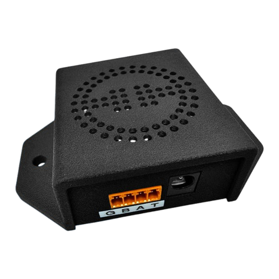
Schneider PM3255 Power Meters* Socomec Diris A10 Janitza UMG104 *Other Types On Request 3.3 OVERVIEW AND DESCRIPTION The front of the Apex DNP3 device has a connector for RS485, labelled as follows: Terminal Label Function Ground RS485 “B” RS485 “A”... -
Page 7: Installation
There is also a USB port which is not used. FUNCTIONALITY The DNP3 device is designed for management and control of hardware at site level. It provides the required reporting and control required by your PUC. The following table describes some of the primary features and functions:... -
Page 8: Planning The Installation
The DNP3 device should be fixed onto a firm surface. WIRING OF THE DNP3 DEVICE Each side of the DNP3 device has a row of connectors. These are used for connecting both the measurement signals and the communications, as follows: Device power: The DNP3 device is powered from 230V via the included power supply. -
Page 9: Commissioning And Operation
LEDs. The Apex DNP3 device requires our engineers to configure the device for you once it has been connected into your site and has a transparent internet connection. With this in place, you may now proceed to commissioning with remote... -
Page 10: Cleaning And Maintenance
APEX Diesel / PV controller “LITE” up to 250kw 8. WARRANTY The Apex DNP3 device is warranted to be free from defects for a period of 2 years from purchase, subject to Apex’s Warranty terms and conditions, a copy of which is available at www.apexsolar.tech 9. -
Page 11: Contact Details
DNP3 Device 9.2 CONTACT DETAILS Telephone: +27 (0) 80 782 4266 Online: https://www.rubiconsa.com/pages/support Email: support@rubiconsa.com Address: Rubicon SA 1B Hansen Close, Richmond Park, Cape Town, South Africa You can reach technical support by telephone directly Monday to Friday between 08h00 and 17h00 (GMT +2 hours).
Need help?
Do you have a question about the DNP3 and is the answer not in the manual?
Questions and answers