Table of Contents
Advertisement
Quick Links
Advertisement
Table of Contents

Related Manuals for EURA DRIVES E2400


Summary of Contents for EURA DRIVES E2400
-
Page 2: Table Of Contents
CONTENTS I. Product ……………………………………………………………… 1.1 Product model naming rule…………………………………………… 1.2 Optional function naming rule………………………………. ……… 1.3 Nameplate …………………………………………………………… 1.4 Appearance…………….…………………………………………… 1.5 Technical Specifications ……………………………………………… 1.6Safe Instructions…………………………………………………… 1.7 Precautions………………………………………………………… 1.8 Examination and Maintenance…………………………..…………… II. Keypad panel……………………………………………………….. … 2.1 Panel Illustrations………………………………………………… III. Installation & Connection …………………………………………… 3.1 Wiring Recommended………………………………………………... -
Page 3: Product
This manual offers a brief introduction of the installation connection for E2000 series inverters, parameters setting and operations, and should therefore be properly kept. Please contact manufacturer or dealer in case of any malfunction during application. 1.1 Product model naming rule E2400 – 0004 S2 CPX Mark Structure ……... -
Page 4: Nameplate
For structure code CPX~CP2, P6 represents protection level IP66, no P6 represents protection level IP55. 1.3 Nameplate Taking for instance the E2400 series 37kW inverter with 3-phase input, its nameplate is illustrated as Fig 1-1. 3Ph: 3-phase output; 75A, 37kW: rated output current and power;... -
Page 5: Appearance
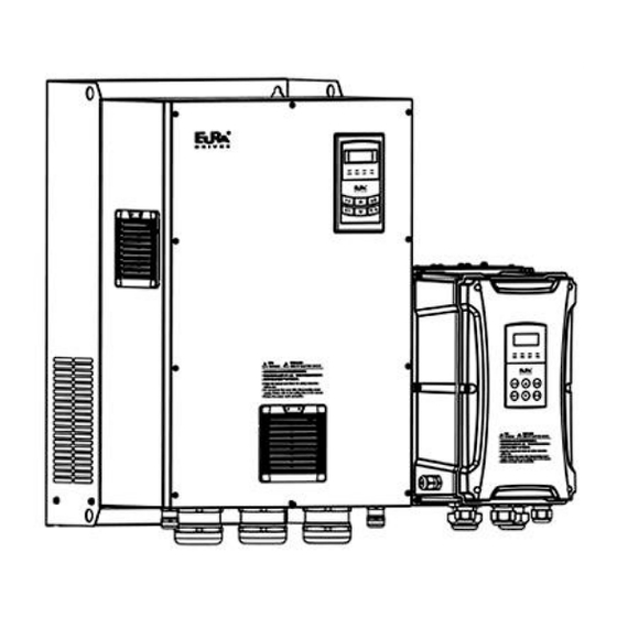
For structure code CP3~CP11, pretection level is IP54. 1.4 Product appearance 1.4.1 Appearance The external structure of E2400 series inverter is classified into plastic and metal housings. Wall hanging type is adopted. Plastic housing possesses elegant appearance and high strength.Taking E2400-0075T3CP1... -
Page 6: Technical Specifications
Metal housing possesses elegant appearance and high strength. Taking E2400-1320T3CP6 for instance, its appearance and structure are shown as in below Fig. Note Keypad Cover Raditor Protective net cover Screw Cable gland Note : Protective net cover is only adopted for 132kW and above 132kW drive. - Page 7 Protection CP3~CP11: IP54 level Applicable 0.4~450kW Motor Note: E2400 series is suitable for harsh indoor environments, such as dust, graphite, and humidity. E2400 series cannot completely prevent dust from entering, but the amount of entering dust will not affect the...
-
Page 8: Safe Instructions
normal operation and will not affect safety. 1.6 Safe instructions ⚫ Please check the model in the nameplate of the inverter and the rated value of the inverter. Please do not use the damaged inverter in transit. ⚫ Installation and application environment should be free of rain, drips, steam, dust and oily dirt; without corrosive or flammable gases or liquids, metal particles or metal powder. -
Page 9: Precautions
1.7. Precautions 1.7.1 Instructions for use ⚫ Never touch the internal elements within 15 minutes after power off. Wait till it is completely discharged. ⚫ Input terminals R, S and T are connected to power supply of 400V while output terminals U, V and W are connected to motor. -
Page 10: Examination And Maintenance
Iout 100% ( m ) 1000 2000 3000 Fig 1-7 Derating Drive’s output current with altitude Fig 1-7 Derating drive’s output current with altitude 1.7.2 Special Warning!! ⚫ Never touch high-voltage terminals inside the inverter to avoid any electric shock. ⚫... - Page 11 inverter. Daily maintenance is necessary to inverters. Daily inspecting: ⚫ Inspecting for noise of motor when it is working. ⚫ Inspecting for abnormal vibration of motor when it is working. ⚫ Inspecting for the installing environment of inverter. ⚫ Inspecting for the fan and inverter temperature. 1.8.4 Daily cleaning: Keep the inverter clean.
-
Page 12: Keypad Panel
II.Keypad panel Two kinds of controllers (four lines of LCD and LED segment display) are available for E2000 series inverters. Refer to note for Fig3-1. 2.1 Panel Illustration 2.1.1 Six- key LED keypad The panel covers three sections: data display section, status indicating section and keypad operating section, as shown in Fig. - Page 13 “Run” and “Stop/Reset” keys control start stop. Press “Stop/Reset” key to reset inverter when in fault status. Press ”FWD/REV” to change motor running direction. Fig.2-3 Operation Panels Note : Nine-key LED keypad and LCD keypad is not supported by E2400 series.
-
Page 14: Installation & Connection
III.Wiring Recommended 3.1 Power cable Table 3-1 Lead Section Area Inverter Model Lead Section Area(mm E2400-0004S2 E2400-0007S2 E2400-0015S2 E2400-0022S2 E2400-0004T2 E2400-0007T2 E2400-0015T2 E2400-0022T2 E2400-0004T3 E2400-0007T3 E2400-0015T3 E2400-0022T3 E2400-0030T3 E2400-0040T3 E2400-0055T3 E2400-0075T3 E2400-0110T3 E2400-0150T3 E2400-0185T3 E2400-0220T3 E2400-0300T3 E2400-0370T3 E2400-0450T3 E2400-0550T3 E2400-0750T3... - Page 15 E2400-0900T3 E2400-1100T3 E2400-1320T3 E2400-1600T3 E2400-1850T3 E2400-2000T3 E2400-2200T3 E2400-2500T3 E2400-2800T3 E2400-3150T3 E2400-3550T3 E2400-4000T3 E2400-4500T3 Table 3-2 Recommended stripping length and Tube cable lug Power cable Grounding cable Inverter model Terminal screw Tube cable lug Terminal screw Tube cable lug E2400-0004S2 RNB2.5-4 RNB2.5-4...
- Page 16 E2400-0040T3 RNB4-5 RNB4-5 E2400-0055T3 SC6-6 SC6-6 E2400-0075T3 SC6-6 SC6-6 E2400-0110T3 SC16-6 SC16-6 E2400-0150T3 SC16-6 SC16-6 Power cable Grounding cable Model Cable fixing Stripping Cable fixing Stripping length mode length(mm) mode (mm) E2400-0185T3 Line pressing 16.5 Line pressing 16.5 E2400-0220T3 Line pressing 16.5...
-
Page 17: Lead Section Area Of Protect Conductor(Grounding Wire)
E2400-3550T3 GTNR240-16 GTNR150-12 E2400-4000T3 GTNR240-16 GTNR240-12 E2400-4500T3 GTNR240-16 GTNR240-12 3.2 Lead section area of protect conductor (grounding wire) Min lead section area of Lead section area S of U,V,W (mm /PE/E(mm2) S≤16 16<S≤35 35<S 3.3 Overall Connection and “Three- Line” Connection *... -
Page 18: Safety Capacitor Group And Varistor Jumper
Note: 1. Please only connect power terminals L1/R and L2/S with power grid for single-phase inverters. 2. 485 communication port has built-in standard MODBUS communication protocol. Communication port is on the left side of inverter. For 30KW inverter and below, the sequence from top to down is B-, A+, 5V power, and GND. For 37KW inverter and above, the sequence from top to down is GND, 5V power, A+, B-. - Page 19 varistor jumper to valid state, by switching to connect pin 2 and pin 4 with a jumper. Note:①when the frequency inverter is applied to the IT power grid system, that is, isolated neutral system, the ground jumper of varistor (screen printed Y1, labeled VAR) and safety capacitor (screen printed J1, labeled EMC) must be adjusted to invalid state.
-
Page 20: Analog Input And Output
IV.Analog Input and Output 4.1 Analog output E2400 series inverters have 2 analog output channels AO1 and AO2. Analog output terminal AO2 can only output current signal, AO1 terminal can output voltage and current signal, the selecting switch is J5, please refer to Fig 4-1, the output relation is shown in table 4-1. - Page 21 Note: There is a black two-digit coding switch SW2 near the control terminal block of E2400 inverter, as shown in Figure 4-5. Turn switches 1 to ON and 2 to ON as illustrated in the figure, the CM, GND terminal of control board is connected to grounding terminal PE.
-
Page 22: Control Terminal
V.Functions of control terminals 5.1 Control terminal The key to operate the inverter is to operate the control terminals correctly and flexibly. Certainly, the control terminals are not operated separately, and they should match corresponding settings of parameters. This chapter describes basic functions of the control terminals. The users may operate the control terminals by combining relevant contents hereafter about “Defined Functions of the Terminals”. - Page 23 Power: 24± 1.5V, grounding is CM; current is restricted below 200mA for Control power Power supply supply external use. When this terminal is valid, the inverter will have jogging running. The jogging function of this terminal is valid under both at stopped Jogging terminal and running status.
-
Page 24: Terminal Two-Line/Three-Line Operation
first and end drive is set to ON state, other drives are set to OFF state. The shielding layer uses single-point reliable grounding. Switch J11 5.2 Terminal two-line/three-line operation control Setting range: 0: No function F208 1: Two-line operation mode 1; Terminal Mfr’s value: 0 2: Two-line operation mode 2;... - Page 25 Running command Stop Stop Forward running Reverse running 3. Three-line mode 1: In this mode, X terminal is enable terminal, the direction is controlled by FWD terminal and REV terminal. Pulse signal is valid. Stopping commands is enabled by opening X terminal. SB3: Stop button SB2: Forward button.
-
Page 26: Trouble Shooting
VI. Trouble Shooting When malfunction occurs to inverter, don’t run by resetting immediately. Check any causes and get it removed if there is any. Take counter measures by referring to this manual in case of any malfunctions on inverter. Should it still be unsolved, contact the manufacturer. - Page 27 Current zero *Flat cable is loosened. *check the flat cable. 15: Err4 excursion *Current detector is broken. *ask for help from manufacture. malfunction * Motor is broken Output * check if wire of motor is loose. 17: PF0 * Motor wire is loose. Phase loss * check if motor is broken.
- Page 28 Motor Malfunction and Counter Measures Malfunction Items to Be Checked Counter Measures Wiring correct? Setting correct? Too big with Get connected with power; Check Motor not Running load? Motor is damaged? Malfunction wiring; Checking malfunction; Reduce protection occurs? load; Check against Table 1-1 Wrong Direction of U, V, W wiring correct? To correct wiring...
-
Page 29: Products And Structure
E2000 VII. Products & Structures Table 7-1 Product structure list of E2400 Structure External Dimension Mounting Mounting Remarks note1 Code Size Bolt [A× B(B1)× H] (W× L) 130*162 144× 179× 227(249) 164× 184× 261(285) 149*193 170*216 185× 206× 293(319) 208× 245× 327(360)... - Page 30 E2000 Product list of E2400 Table 7-2 Applicable Rated Current Structure Cooling Model Remarks Model Motor (kW) Output Code Mode E2400-0004S2 Self-cooling E2400-0007S2 0.75 Air-cooling E2400-0015S2 Air-cooling E2400-0022S2 10.0 Air-cooling E2400-0004T2 Self-cooling E2400-0007T2 0.75 Air-cooling E2400-0015T2 Air-cooling E2400-0022T2 10.0 Air-cooling...
- Page 31 E2000 E2400-1600T3 Air-cooling E2400-1850T3 Air-cooling E2400-2000T3 Air-cooling E2400-2200T3 Air-cooling E2400-2500T3 Air-cooling E2400-2800T3 Air-cooling E2400-3150T3 CP10 Air-cooling E2400-3550T3 CP10 Air-cooling E2400-4000T3 CP11 Air-cooling E2400-4500T3 CP11 Air-cooling Fig 7-1 Plastic hanging profile...
- Page 32 E2000...
- Page 33 E2000 Fig7-2 Metal hanging profile Note 1: H1 is the overall dimension including the cable gland.
-
Page 34: Zoom Table Of Function Code
E2000 VIII. Zoom Table of Function Code Basic parameters: F100-F160 Function Function Chang Mfr’s Value Setting Range Code Definition User’s Password √ F100 0~9999 Inverter’s Rated Current (A) F102 Subject to inverter model F103 Inverter Power (kW) Subject to inverter model F104 Voltage level Subject to inverter model... - Page 35 E2400 √ F127 Skip Frequency A 0.00~650.0Hz 0.00 √ F128 Skip Width A ± 2.50Hz 0.00 √ F129 Skip Frequency B 0.00~650.0Hz 0.00 √ F130 Skip Width B ± 2.50Hz 0.00 0-Present output frequency / function code 1 - Current output rotary speed 2-Output current...
- Page 36 E2400 0: Linear compensation; 1: Square compensation; 2: User-defined multipoint ╳ F137 Modes of torque compensation compensation 3: Auto torque compensation 4: V/F separation subject to inverter ╳ F138 Linear compensation 1~20 model 1:1.5; 2:1.8; ╳ F139 Square compensation 3:1.9;...
- Page 37 E2400 Reading accessorial frequency △ F158 polarity 0: Control speed normally; Random carrier-wave F159 1: Random carrier-wave frequency selection frequency 0: Invalid 1: Valid Reverting to manufacturer ╳ 21: revert user macro 1 F160 values 22: revert user macro 2 Running control mode: F200-F230 0: Keypad command;...
- Page 38 E2400 Reference for selecting 0: Relative to max frequency; ╳ accessorial frequency source Y F205 1: Relative to main frequency X range ╳ 0~150 F206 Accessorial frequency Y range 0: X; 1: X+Y; 2: X or Y (terminal switchover); 3: X or X+Y (terminal switchover);...
- Page 39 E2400 √ X+Y-50% (%) 0~200 F221 √ F222 count memory selection Setting range: 0: Invalid 1: Valid √ F223 Main frequency coefficient 0.0~100.0 100.0 When target frequency is lower 0: stop F224 × than Min frequency 1: run at min frequency...
- Page 40 E2400 √ 0~50.00% 30.00 F249 Jump frequency √ 0.1~3000 10.0 F250 Rising time of traverse (S) √ 0.1~3000 10.0 F251 Descending time of traverse (S) √ F112~F111 3.00 F252 Crawl-positioning frequency (Hz) √ 0.0~3000 Waiting time of crawl-positioning F253 √...
- Page 41 E2400 √ F303 DO output types selection 0: level output 1 : pulse output curve beginning stage √ F304 2.0~50.0 30.0 proportion √ F305 S curve ending stage proportion 2.0~50.0 30.0 ╳ F306 Accel/decel mode 0:Straight-line 1: S curve √...
- Page 42 E2400 24: clear traverse status 25: Traverse operating mode is valid. 26: yarn broken 27: intertwining yarn 28: crawl-positioning signal 29: clear actual yarn length and traverse status 30: Water lack signal; 31: Signal of water 32: Fire pressure switchover;...
- Page 43 E2400 AO2 output simulation Setting range: 0~4095 ╳ F339 0: Invalid 1: DI1 negative logic 2: DI2 negative logic 4: DI3 negative logic Selection of terminal negative √ 8: DI4 negative logic F340 logic 16: DI5 negative logic 32: DI6 negative logic...
- Page 44 E2400 Analog Input and Output: F400-F480 ○ F400 Lower limit of AI1 channel input (V) 0.00~F402 0.04 Corresponding setting for lower limit of AI1 √ F401 1.00 0.00~2.00 input ○ F402 Upper limit of AI1 channel input (V) F400~10.00 10.00 Corresponding setting for upper limit of √...
- Page 45 E2400 0: Potentiometer in local panel √ F422 Potentiometer selection 1: Potentiometer in remote control panel √ 0: 0~5V; 1: 0~10V or 0-20mA F423 AO1 output range 2: 4-20mA √ F424 AO1 lowest corresponding frequency 0.0~F425 0.05 √ F425 AO1 highest corresponding frequency F424~F111...
- Page 46 E2400 Corresponding setting of FI max √ F443 Max(1.00,F441)~2.00 2.00 frequency F444 Reserved √ F445 Filtering constant of FI input pulse 0~100 √ F446 FI channel 0Hz frequency dead zone 0~F442Hz (Positive-Negative) 0.00 0.001~2.000 1.000 √ F448 F1 proportional gain √...
- Page 47 E2400 Multi-stage Speed Control: F500-F580 0: 3-stage speed; 1: 15-stage speed; ╳ F500 Stage speed type 2: Max 8-stage speed auto circulating Selection of Stage Speed Under √ F501 2~8 Auto-circulation Speed Control 0~9999(when the value is Selection of Times of Auto- Circulation √...
- Page 48 E2400 1: Stage speed mode 2 Auxiliary Functions: F600-F677 0: Invalid; 1: braking before starting; √ F600 DC Braking Function Selection 2: braking during stopping; 3: braking during starting and stopping √ F601 Initial Frequency for DC Braking 0.20~50.00 1.00 √...
- Page 49 E2400 Setting range: 0: invalid √ F631 VDC adjustment selection 1: valid at stable running 2: reserved 3: valid at any time Subject √ Target voltage of VDC adjusting F632 Setting range: 100~2300 inverter model √ 5.00 frequency of VDC adjusting F633 Setting ragne: 0~100.00...
- Page 50 E2400 2: Target rotate speed 3: Output current 4: Output voltage 5: PN voltage 6: PID setting value 7: PID feedback value 8: Radiator temperature 9: Count value 10: Linear speed Main frequency setting channel 12: Main frequency 13: Auxiliary frequency setting...
- Page 51 E2400 0.0: F114 0.0~3000s √ F659 Voltage rally deceleration time 0.0: F115 200~F661 Subject to Action judging voltage at × 〇 F660 inverter model instantaneous power failure F660~1400 Subject to Action stop voltage at × 〇 F661 inverter model instantaneous power failure Instantaneous voltage recovery √...
- Page 52 E2400 Delay time for free stop and √ F701 0.0~60.0s programmable terminal action 0:controlled by temperature 1: Running when inverter is ╳ Fan control mode F702 powered on 2: Controlled by running status Inverter Overloading pre-alarm F704 50~100 Coefficient (%) ╳...
- Page 53 E2400 △ Fault Current of Last Malfunction but F718 △ Fault PN Voltage of Last Malfunction F719 but Two Record of overcurrent protection fault △ F720 times △ Record of overvoltage protection fault F721 times Record of overheat protection fault △...
- Page 54 E2400 √ F755 Duration time of zero-current 0~60 × F759 Carrier-frequency ratio 3~15 F760 Grounding protection 0: Invalid 1: Valid F761 Switchover mode of FWD/REV 0: At zero 2: at start frequency × △ F770 Auxiliary version No. F771 Precharge function 0: invalid 1:valid ×...
- Page 55 E2400 Subject to inverter √ F815 Rotary speed loop KP2 1~100 model √ F816 Rotary speed loop KI2 0.01~10.00 1.00 √ F817 PID switching frequency 1 0~F818 5.00 √ F818 PID switching frequency 2 F817~F111 10.00 √ F819 Slip coefficient...
- Page 56 E2400 PMSM injection current × 〇 compensation without load F877 0.0~50.0 PMSM cut-off point of injection current × 〇 F878 0.0~50.0 10.0 compensation without load PMSM injection current with × 〇 F879 0.0~100.0 heavy load (%) PMSM PCE detection time ×...
- Page 57 E2400 Ones: slave fault information 0: Not sending fault information √ F914 Fault information of slave 1: Sending fault information Tens: master’s reaction when it loses slave’s response 0: No reaction 1: Alarm 0: continue running Master action when salve √...
- Page 58 E2400 0~65535 √ F933 BACnet device number 0.0~10.0 Master/slave adjustment time √ F934 benchmark(S) 0.0~50.0 Master/slave adjustment √ F935 current error(%) 0: mode 0 1: mode 1 Adjustment mode × F936 accel/decel 0: no adjustment Current balance Slave adjustment frequency ×...
- Page 59 E2400 Min limit of PID adjusting √ FA05 0.0~FA04 0: Positive feedback ╳ FA06 PID polarity 1: Negative feedback FA07 Dormancy function selection 0: Valid 1: Invalid ╳ frequency √ Max(F112, 0.1)~F111 5.00 FA09 adjusting (Hz) FA10 Dormancy delay time (S) 0~500.0...
- Page 60 E2400 0: no switchover 1: reserved × FA41 PI parameter switchover type 2: Auto switchover 3: reserved FA42 Switchover error 1 FA05~FA43 √ FA43 Switchover error 2 FA42~FA03 √ The sequence of starting No ╳ 1~20 FA47 1 relay The sequence of starting No ╳...
- Page 61 E2400 5: Reserved ╳ FC07 Torque given coefficient 0~3.000 3.000 FC08 Reserved √ FC09 Torque given command value (%) 0~300.0 100.0 FC10- Reserved FC13 0: Digital given (FC17) ╳ FC14 Offset torque given channel 1: Analog input AI1 2: Analog input AI2...
- Page 62 E2400 √ FC30 Electric torque limited (%) 200.0 0~300.0 0: Digital given (FC35) 1: Analog input AI1 2: Analog input AI2 ╳ FC33 Braking torque limited channel 3: Analog input AI3 4: Pulse input channel FI 5: Reserved ╳ FC34 Braking torque limited coefficient 0~3.000...
- Page 63 E2400 The second motor parameters: FE00-FE84 Ones: motor selection 0: No. 1 motor 1: No. 2 motor 2: Terminal switchover Tens: control mode of No.2 motor FE00 Motor switchover × 0: sensorless vector control (SVC) 1: Closed-loop vector control (VC)
- Page 64 E2400 √ FE17 Motor 2 switching frequency 1 0.00~F818 5.00 √ FE18 Motor 2 switching frequency 2 FE17~F111 10.00 0: same with accel/decal time of motor 1 √ FE19 Accel/decel time of motor 2 1: 1 accel/decal time 2: 2ed accel/decal time...
- Page 65 E2400 FE44 Motor 2 fault PN voltage of △ last malfunction but two(V) FE45 Motor 2 record of overcurrent △ protection fault times FE46 Motor 2 record of overvoltage △ protection fault times FE47 Motor 2 record of overheat △...
- Page 66 E2400 √ FF08 Expansion input DID 0: Invalid 1: DIA negative logic Expansion input negative logic √ FF09 2: DIB negative logic selection 4: DIC negative logic 8: DID negative logic Parameters display: Running frequency / target △ H000 frequency (Hz) Speed with load / target △...
- Page 67 E2400 △ H024 Reserved △ H025 Power-On time (h) △ H026 Running time (h) △ H027 Input pulse frequency(Hz) △ H028 Reserved △ H029 Reserved △ H030 Main frequency X(Hz) △ H031 Accessorial frequency Y(Hz) △ H032 Torque sent by master △...
- Page 68 E2400 Please set F800=2 for stationary parameter measurement. Operation of one inverter with multiple motors is not supported in this mode 5. When F641>0 and low-frequency oscillation suppression is effective, a frequency inverter can only drive one motor at the same time, and motor parameters must be set correctly (F801~F805, F844) 6.
Need help?
Do you have a question about the E2400 and is the answer not in the manual?
Questions and answers