
Related Manuals for EURA DRIVES EM30 Series


Summary of Contents for EURA DRIVES EM30 Series
- Page 1 FREQUENCY INVERTER EM30 0,4kW – 7,5kW Safety instructions Installation & operating manual ENGLISH EM30 – Rev.03 -D- SOFT Rev. 1.1x www.eu r adr ives.e u © 2017 EURA Drives GmbH...
- Page 2 INDEX PAGE 1) Common installation- and safety rules for series EM30 inverters 2) Product data / product power range 3) Inverter mounting 4) Electrical connection of EM30 inverters 5) Control-board – hardware and I/O channel configuration 6) Operating panel 7) Inverter parameter setting 8) Parameter group 100: Basic parameter 9) Parameter group 200: Inverter control 10) Parameter group 300: Digital I/O configuration...
- Page 3 1) Common installation rules and safety information regarding EURA EM30 inverters 1) Common installation- and safety rules for EURA DRIVES inverters, series EM30 IMPORTANT !! This instruction manual explains rules for correct installation and safe operation of frequency inverters, series EM30 (denominated inverter, or drive in the following guidance). It is mandatory to follow exactly, what reported in this instruction manual.
- Page 4 Harmonized standards EN50178 (VDE160) and EN60439-1 (VDE0660, T. 500) are applied. EURA DRIVES EM30 is a product with limited availability (in sense of IEC 61800-3). Frequency inverters may create high frequency noise, in case the operator is responsible for proper countermeasures.
-
Page 5: Handling, Transportation And Storage
1) Common installation rules and safety information regarding EURA EM30 inverters Handling, transportation and storage Inverter components may become damaged and insulating distances may be reduced, as a result of improper transportation, handling or DANGER storage of the drive. In this case, the inverter does not anymore comply with product specific standards and rules, and it is not allowed to place it into operation. - Page 6 1) Common installation rules and safety information regarding EURA EM30 inverters LVD – DOUBLE INSULATON All connection terminals for control and feed-back are single insulated in sense of EN50178. In case of connection to external equipment with double insulation, the user has to provide proper arrangement, to guarantee double insulation in sense of EN50178 for the whole system EP66 inverters are designed for steady state installation, using fixed GROUNDING...
- Page 7 1) Common installation rules and safety information regarding EURA EM30 inverters Braking resistors DANGER OF FIRE All kinetic energy of the system converts to heat, during braking cycle. BURNS This energy dissipates in the braking resistor. Improper dimensioning of the braking resistor or insufficient heat exchange may result in high risk if fire Also over-voltage on the input power supply my lead to high risk of fire...
- Page 8 1) Common installation rules and safety information regarding EURA EM30 inverters Basic rules for reliable and safe operation -Proper dimensioning of the system (motor, inverter, mechanical elements). -Check for correct inverters rated voltage, consider tolerances too -Review all inverter and motor cabling, including correct terminal tightening torque (torque values: see table).
- Page 9 1) Common installation rules and safety information regarding EURA EM30 inverters Power-grid specification: The inverter is build for symmetric three phase power supply systems, with voltage phase to earth/neutral not exceeding 300V. A transformer can be used for adaptation to higher voltages. For single phase inverters the maximum input voltage is 240V +15%, 400V class thee phase inverters can work up to 460V +15%.
- Page 10 1) Common installation rules and safety information regarding EURA EM30 inverters EMC: Basics and recommendations for installation The EM30 series inverters are electrical devices, designed for installation in industrial area. EM30 inverters are not designed to work stand alone, these inverters are considered as part of a complex system, for this reason, no separate EMC marking is applied on the inverter.
- Page 11 1) Common installation rules and safety information regarding EURA EM30 inverters Inverters with UL mark: Additional information EM30 – Rev.03 -EN- SOFT Rev. 1.1x - 9 - © 2017-06-KPP-EURADRIVES EUROPE GmbH...
-
Page 12: Product Data / Product Power Range
2) Product data / Product naming convention 2) Product data / product power range Product naming convention Basic product code: EM30 0007 T3 J1 EM30 Inverter series (EM30) 0007 Inverter power code Power code 0004 0007 0011 0015 0022 0030 0040 0050 0075... -
Page 13: Mechanical Construction
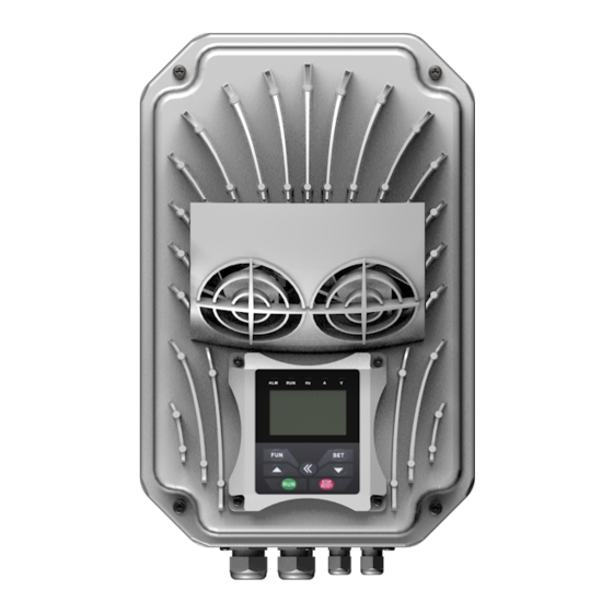
2) Product data / Product naming convention Mechanical construction EM30 inverter are based on a die-cast aluminium frame. The frame has a flange attack, used to mount the inverter directly on the terminal-box of the motor. Mounting is done by using specific adapter plates, depending on motor geometry (see chapter: inverter mounting) The basic frame holds the cable conduit plate, the... - Page 14 2) Product data / Product naming convention Technical data - inverter series E30 Rated voltage 3-phase 380…460V +/- 15% - 1phase 230V +/- 15% Power supply Input frequency 44….67 Hz EMC filter Integrated for 2. environment - optional for 1st environment Output voltage 0……...U-input Output frequency...
- Page 15 2) Product data / Product naming convention Product range, framesizes: 230V single phase EM30-0004S2 J1 0,4 kW - 2,5A EM30-0007S2 J1 0,75 kW - 4,5A 190x270165 80 Ohm EM30-0015S2 J1 1,5 kW - 7A EM30-0022S2 J1 2,2 kW - 10A 400V three phase EM30-0007T3 J1 0,75 kW - 2 A...
-
Page 16: Inverter Mounting
3) Inverter mounting 3) Inverter mounting Please read all, what reported on chapter 1) Common installation- and safety rules for EURA DRIVES inverters, series before EM30 proceeding with inverter mounting, cabinet wiring, and putting into service the system. Motor mounting EM30 inverters have IP66 Protection class and are build for direct mounting on the motor. -
Page 17: Wall Mount
If wallmount is required, a specific wallmount kit is available - please refer to extra instruction Maintenance and service: Inverters of the EM30 series may have forced ventilation (depending on power range). The fans are maintenancefree and have protection degree IP66 Ventilation channels and heatsink fins should be checked for dirt and dust, and cleaned on a regular basis. -
Page 18: Power Terminals
4) Electrical connection of EM30 inverters EM30 series inverter have IP66 class protection. All connection terminals are located inside the enclosure. All control an power cables pass through a removable cable conduit plate, this plate can be used for shield connection as well, using proper cable glands with shield contacts. - Page 19 4) Electrical connections of EM30 inverters Inverter size J1 400V 0,75 - 3,0 kW Inverter size J3 400V 4,0 - 7,5 kW EM30 – Rev.03 -EN- SOFT Rev. 1.1x - 17 - © 2017-06-KPP-EURADRIVES EUROPE GmbH...
-
Page 20: Brake Resistor
4) Electrical connections of EM30 inverters Brake resistor: EM30 inverters have build in chopper transistor as standard. An adequate brake resistor can be connected externaly. The maximus lenght of the cable is 2mt, crossection depends on the current through the resistor, calculated, considering the brake switch on voltage of 800V and the resistor value. - Page 21 4) Electrical connections of EM30 inverters Recommended cable cross sections, fuses, terminal tightening torque Inverter Input Cable cross section Input fuses model current AWG) terminal tightening torque UL-Klasse T Bussmann-Typ / AWG / lbs/inch 60269 gG (A) EM30-0007T3 J1 JJS10 EM30-0015T3 J1 2,5 / AWG14 /10...
- Page 22 4) Electrical connections of EM30 inverters Control terminals – control board J1/ J2 Inverter size EM30 – Rev.03 -EN- SOFT Rev. 1.1x - 20 - © 2017-06-KPP-EURADRIVES EUROPE GmbH...
- Page 23 4) Electrical connections of EM30 inverters Control terminal function and factory default configuration Terminal Type Description Hardware data Parameter DEFAULT Programmable Open-Collector output, max. 100mA-24V (F301) (F303) Message F=>0Hz digital output 1 (referred on CM) – Pulse output Digital Relays output - isolated (F300/F302) Fault signal...
- Page 24 4) Electrical connections of EM30 inverters Sample set-up for inverter 3 kW 400V J1 If parameter status is unknown, factory reset is recommended: Set parameter F160 = 1 AI1: Analogue speed reference 0..10V (potentiometer) through input channel Set F203=1 START/STOP command and inversion through terminal signals: set F208=2 (two wire control) "Inverter ready signal on relays 1 contact: F300=13 „Inverter enabled“...
- Page 25 5) Control board – hardware and I/O channel configuration 5) Control-board: hardware and I/O channel configuration I/O channel configuration is a combination of hardware and software setting For software parameter setting see chapter: 10) Parameter group 300: Configuration of digital I/O channels 11) Parameter group 400: Configuration of analogue I/O channels EM30 Control-board Digital input channels, PNP/NPN setting:...
- Page 26 5) Control board – hardware and I/O channel configuration Analogue input channels: and AI2, both have a resolution of 12 Bit. EM30 have two independent analogue input channels Signal type and level configuration is done by hardware setting on the control board, and corresponding parameter setting.
- Page 27 5) Control board – hardware and I/O channel configuration Inverters of the EM30 series have two relay contact output, and one open collector output DO1, both are free programmable for different functions, assignation codes are set in parameters F300 – F302.
-
Page 28: Inverter Status
6) Operating panel 6) Operating panel – configuration and functions Inverter control, parameter setting, operating-parameter display and inverter-status information are all done by the operation panel. The adjacent picture shows the different areas of the panel: Inverter status indication Backlight 4 Line character display F646 Parameter to set backlight time... -
Page 29: Normal Operating Mode
6) Operating panel 4 Line character display: Three operating modes: Normal operating mode: Primary display, line 1 and 2: The content of the display is defined by parameter F645 – value, description and units of the defined operating parameter are shown Secondary display in line 3 and 4: It displays various operating parameters in START/STOP mode. -
Page 30: Parameter Setting
7) Inverter programming 7) Parameter setting For easier parameter setting, the whole parameter list is divided into 11 parameter groups: Parameter. Nr. Range Group Parameter type BASIC parameter F100 - F160 Inverter control, set-point source setup F200 - F280 Function assignation to digital I/Os - diagnosis F300 - F340 Analogue I/O signal configuration F400 - F473... -
Page 31: Parameter Group 100: Basic Parameter
8) Parameter group 100: Basic parameter 8) Parameter group 100: Basic parameter F100 Passwort Range: 0 – 9999 Default: 8 If F107=1 (password enabled): enter correct password, to unlock parameter modification function. Incorrect password results in on the display Err1 F102 Rated current (A) Range: 1.0 –... - Page 32 8) Parameter group 100: Basic parameter F113 Internal speed reference (Hz) Range: F112 - F111 Default setting: 50.00 Hz Virtual internal speed reference, it is selectable in the same way, as any external speed reference (see F203, F204). If selected F203/204 = 0, after the START command, the inverter will reach this speed value.
- Page 33 8) Parameter group 100: Basic parameter F124 Jog frequency (Hz) Range: F112 - F111 Default setting: 5.00 Hz F125 Default setting: 0.2 - 3.7KW: 5.0 sec. Accel. ramp – Jog Mode (sec.) Range: 5.5 - 30KW: 30.0 sec. 0.1 – 3000 sec. F126 Decel.
- Page 34 8) Parameter group 100: Basic parameter Target frequency / Parameter (Fxxx) Jog modus via keypad - HF-0 Target motor speed (rpm) DC-voltage PID control feed back F132 Heatsink temperature Display: Selection of operating Default setting: Counter parameters to display during „STOP“ status 0+2+4=6 PID set-point (Motor stopped)
- Page 35 8) Parameter group 100: Basic parameter F136 Slip compensation in V/Hz mode Range: 0 - 10% Default setting: 0 This parameter compensates the load-depending slip of the asynchronus motor – it works only in the stable area of the motor speed/torque characteristic during the "catch on the fly"...
- Page 36 8) Parameter group 100: Basic parameter F140 BOOST knee-frequency (Hz) Range: 0 – 5 Hz Default setting: 1 Hz F141 BOOST intensity (%) Range: 0 – 25% Default setting: 4 % BOOST function allow additional voltage increase on low speed – see graphic (for F137=0 or F137=1). F152 Maximum motor voltage (at knee frequency –...
-
Page 37: Parameter Group 200: Inverter Control
9) Parametergroup 200: Inverter control 9) Parameter group 200: Inverter control START / STOP / running direction: Attention: RUN/STOP commands, as set in parameter F200 and F202 work with dynamic signals (pulses). In Europe it is more common to work with static signals (for safety reason). Therefore it is recommended to use RUN/STOP signals, defined by parameter F208 (two wire control) F208 overwrites parameter F200/201 Selection: 0: Keypad only 1: Terminal input only... - Page 38 9) Parametergroup 200: Inverter control Selection: 0: Internal reference (F155) – with memory 1: Analogue input AI1 F204 Secondary speed- 2: Analogue input AI2 reference source 3:Reserved Default setting: 0 "Y” 4: Fix-frequencies, terminal control (digital inputs) 5: same as 1, (F155) but no memory 6: PID controller output Secondary speed channel has the same function, as primary channel, if selected as the only reference.
- Page 39 9) Parametergroup 200: Inverter control Combination between different speed reference channels 0 Internal 1 External 2 Extern 4 Fix- F204 5 PID digital set with Analogue Analogue frequency controller memory input AI1 input AI2 selection F203 0 Internal digital set ●...
- Page 40 9) Parametergroup 200: Inverter control Two / Three wire control for START - STOP - DIRECTION: This control mode overwrites the setting in F200, F201, F202 Selection: 0: Deactivated Two-wire, Type 1 (static) F208 Activation special Default Two-wire, Type 2 (static) Two / Three wire control setting: 0 Three wire, Typ1 (Impulse / pushbutton control –...
- Page 41 9) Parametergroup 200: Inverter control Selection: 0: STOP controlled by deceleration ramp F209 “STOP” mode selection 1: Free-stop (uncontrolled) Default setting: 0 2: STOP with DC injection If F208=1: STOP command disables the final stage, motor stops uncontrolled by inertia If F208=2: STOP wit DC brake function (defined in F600, F603, F605, F656) ATTENTION: In DC brake mode all kinetic energy will dissipate in the rotor.
-
Page 42: Parameter Group 300: Digital I/O Configuration
10) Parameter group 300: Digital I/O configuration 10) Parameter group 300: Digital I/O configuration Following digital I/O channels are available on EP66 inverters: Digital inputs 6 (DI1…DI6) Parameters F300-F302 (for outputs) and F316– Digital outputs 1 (DO1) Open Collector 100 mA / 24 V F321 (for inputs) allow assignation of various Relay output... - Page 43 10) Parameter group 300: Digital I/O configuration F303 Configuration DO1 as pulse Selection: 0: digital output Default setting 0 output 1: Pulse output F303=1: Output DO1 is configured as fast pulse signal output, with maximum frequency of 50kHz. Signal configuration through parameter F449 - F453.
- Page 44 10) Parameter group 300: Digital I/O configuration Function mapping for digital input channels DI1 – DI6 F316 Default setting (JOG-forward) Function assignation to DI1 F317 Default setting (EMERGENCY-STOP EXT.) Function assignation to DI2 F318 Function mapping: 0….61 Default setting (TERMINAL "FORWARD") Function assignation to DI3 F319 Default setting...
- Page 45 10) Parameter group 300: Digital I/O configuration Fixed-frequencies selection – table 300-1 Frequency Programming parameter Fixed-frequency 1 F504/F519/F534/F549/F557/F565 Fixed-frequency 2 F505/F520/F535/F550/F558/F566 Fixed-frequency 3 F506/F521/F536/F551/F559/F567 Fixed-frequency 4 F507/F522/F537/F552/F560/F568 Fixed-frequency 5 F508/F523/F538/F553/F561/F569 Fixed-frequency 6 F509/F524/F539/F554/F562/F570 Fixed-frequency 7 F510/F525/F540/F555/F563/F571 Fixed-frequency 8 F511/F526/F541/F556/F564/F572 Fixed-frequency 9 F512/F527/F542/F573 Fixed-frequency 10 F513/F528/F543/F574...
-
Page 46: Parameter Group 400: Analogue I/O Channel Configuration
11) Parameter group 400: Analog I/O configuration 11) Parameter group 400: Analogue I/O channel configuration The EM30 control board offers 2 independent analogue input channels. Each of them can be adapted to various input/output signals – all configuration must be done by software/hardware setting Details and instruction for hardware setting: see chapter 5) Control hardware and IO/ channel configuration Following instruction describes, how to set software parameters Configuration of analogue speed reference channels... - Page 47 11) Parameter group 400: Analog I/O configuration Same configuration for F406 Range definition – lower limit (V) Range 0.00V…F408 Default setting: 0.00V F407 Assignation lower limit Range: 0…2.00 Default setting: 1.00 F408 Range definition – upper limit (V) Range: F406…10.00V Default setting: 10.00V F409 Assignation upper limit...
- Page 48 11) Parameter group 400: Analog I/O configuration Pulse speed reference signal input configuration: Configuration is done in the same way, as for analogue speed reference signal. DI1 is predetermined as pulse signal input channel. DI1 selection is done automatically, if pulse reference signal is selected as speed reference source.
- Page 49 11) Parameter group 400: Analog I/O configuration Analogue output configuration AO1, AO2 Selection: 0=0…5V F423 Signal type configuration output 1=0…10V, 0…20mA * Default setting: 1 current/voltage signal 2=4…20mA * F424 Inverter output frequency assigned to Range: 0.0…F425 Default setting: 0.05 Hz minimum output signal on F425 Inverter output frequency assigned to...
-
Page 50: Parameter Group 500: Fixed-Frequency, Automatic Cycling Frequencies
12) Parameter group 500: Fixed-frequency, automatic cycling frequencies 12) Parameter group 500: Fixed-frequency, automatic cycling frequencies Up to 15 fixed-frequencies are selectable on EM30 inverters, including individual ramp and direction setting. Automatic cycling sequence for up to 8 fixed-frequencies can be set, including ramp, direction, run- and pausing time. Set parameter F203=4 (F204=4), to select fixed frequency mode:... -
Page 51: Parameter Group 600: Dc-Bake Control / Aux. Functions
13) Parameter group 600: DC-Brake control / aux. functions 13) Parameter group 600: DC-Bake control / Aux. functions DC-Brake function parameters: Selection: 0: DC-Brake deactivated F600 DC-Brake function 1: DC injection before START Default setting 0 activation 2: DC injection after STOP 3: Before START and after STOP F601 Frequency threshold for... - Page 52 13) Parameter group 600: DC-Brake control / aux. functions Brake Chopper control (internal brake chopper) F612 Max. duty-cycle chopper Range: 0…100 % Default setting: 100 % "Catch on the fly" function: To get already spinning motor controlled (V/Hz mode only) Selection: 0: Function deactivated F613 Activation of the function...
-
Page 53: Main Display Configuration
13) Parameter group 600: DC-Brake control / aux. functions Main display configuration F645 Selection of operating parameters, to display Selection: 0..33 Default setting: 0 in line 1 and 2 Description see table F645 Operating parameter Description Output frequency Speed Speed setpoint Motor current Motor voltage DC-Voltage... - Page 54 13) Parameter group 600: DC-Brake control / aux. functions Power drop compensation F657 Activation of the power drop Selection: 0: deactivated Default setting: 0 compensating function 1: activated F658 Compensation ramp: Accel. Range: 0,0..3000sec. – 0,0=F114 Default setting: 0,0 sec F659 Compensation ramp: Decel.
-
Page 55: Parameter Group 700: Error Handling And Protection Functions
14) Parameter group 700: Error handling and protection functions 14) Parameter group 700: Error handling and protection functions Programmable delay for STOP- DISABLE with STOP signal through terminal Selection: 0: immediate STOP/DISABLE F700 Delay selection Default setting: 0 1: with delay F701 Delay time setting (sec.) Range: 0.0…60.0 sec. -
Page 56: Error History
14) Parameter group 700: Error handling and protection functions ERROR history Error codes ON DISPLAY (error memory code) CODE Description Resaon Remedy Over-current – hardware OC (2) detected Increase Accel/Decel ramp time Too short ramps, short circuit on output Check cabling / motor Over-current –... - Page 57 14) Parameter group 700: Error handling and protection functions Error memory readout: F711 Frequency at last fault (Hz) F708 F712 Current at last fault (A) Last fault F713 DC-Link voltage at last fault (V) F714 Frequency at fault last but one (Hz) F709 Fault code: see table above F715...
- Page 58 14) Parameter group 700: Error handling and protection functions Analogue signal interruption detection Selection 0: deactivated F741 Analogue signal 1: STOP and AErr on display interruption – fault 2: STOP without any message on display Default setting: 0 handling mode 3: Inverter continue running with f-min 4: Reserved F742...
-
Page 59: Parameter Group 800: Autotuning - Motor Data Programming
15) Parameter group 800: Autotuning – Motor data input 15) Parameter group 800: Autotuning – Motor data programming EP66 inverter are designed to drive standard asynchronus motor and Permanent Magnet synchronus motors as well Smart AUTOTUNING functions help for easy and quick setup Basic data for Asynchronus and Synchronus motors Selection: 0: AUTOTUNING deactivated F800... - Page 60 15) Parameter group 800: Autotuning – Motor data input SENSORLESS VECTOR speed controller (for asynchronus motor only) F812 Start excitation time (sec.) Range: 0…30.0 sec. Default setting: 0.3 F813 Proportional gain in Range: 1…100 Default setting: 30 frequency range 1 KP1 F814 Integration time in Range: 0.01…10.00...
- Page 61 Hardware MODBUS - interface : All EURA Drives inverter are equipped with a unique RS485 connector. This port is used for inverter control via MODBUS and for parametrizing the inverter, using PC software or COPY STICK. The picture below shows the pin-out of the 4 pole plug and the position of the connector...
-
Page 62: Parameter Group A00: Pid Controller Parameter
17) Parameter group A00: PID setup 17) Parameter group A00: PID controller parameter An integrated PID-controller is available on standard EM30 inverters. It is suitable for simple closed loop control projects. For more demanding projects, like Booster stations using multi-pump control, cascade control or Master/Slave interaction, specific hard-/software options are available. - Page 63 17) Parameter group A00: PID setup EM30 – Rev.03 -EN- SOFT Rev. 1.1x - 61 - © 2017-06-KPPEURADRIVES EUROPE GmbH...
- Page 64 17) Parameter group A00: PID setup PID controller parameter setting FA19 Proportional gain Range: 0.00…10.00 Default setting: 0.3 FA20 Integration time (sec.) Range: 0.1…100.0 sec. Default setting: 0.3 sec. FA21 Differential time (sec.) Range: 0.00…10.00 Default setting: 0.0 sec. FA22 Controller cycle time / scan-rate (sec.) Range: 0.1…10.0 sec.
-
Page 65: Emergency Functions
17) Parameter group A00: PID setup PID controller secondary parameter set FA38 Proportional gain (2) Range: 0.00…10.00 Default setting: 0.3 FA39 Integration time (2) (sec.) Range: 0.1…100.0 sec. Default setting: 0.3 sec. FA40 Differential time (2) (sec.) Range: 0.00…10.00 Default setting: 0.0 sec. Selection: FA40 PID parameter switchover... -
Page 66: Parameter Group C00: Speed / Torque Control
18) Parameter group C00: Speed / Torque control 18) Parameter group C00: Speed / Torque control Attention: this settings are for SLV mode only F106=0 Two different control modes are available on EM30 inverters: Speed-control mode and Torque-control mode Selection: 0: Speed control FC00 Speed / Torque control mode 1: Torque control... - Page 67 18) Parameter group C00: Speed / Torque control Speed limiting for inverter, working in torque control mode: Selection: 0: Set by FC23 1: Analogue input AI1 2: Analogue input AI2 FC22 Speed limiting set-point origin forward Default setting: 0 3: Analogue input AI3 4: Pulse signal input 5: Reserved FC23...
- Page 68 19) EM30 - Troubleshooting and diagnosis 19) EP66 Diagnostic tools Analogue/Digital input status monitoring The logical status of digital I/O channels is shown in F330 Digit input 8+3 graphical blocs (dark=ON) Digital output The value of the analogue inputs is displayed from Analogue input 0...4096 Analogue output...
- Page 69 In case of not professional installation or use of improper components, EURA Drives cannot guarantee for the proper filter class, and will not assume any responsibility for damage on the inverter or on other components of the system.
- Page 70 NOTES...
- Page 71 NOTES...
- Page 72 Te l . : +4 9 4 0 5 8 9 7 9 50 0 Fa x . : + 49 4 0 5 8 9 79 5 0 2 9 ww w. eu r ad ri v e s . eu EM30 – Rev.03 -D- SOFT Rev. 1.1x © 2017 EURA Drives GmbH...
Need help?
Do you have a question about the EM30 Series and is the answer not in the manual?
Questions and answers