
Related Manuals for EURA DRIVES EM30 Series


Summary of Contents for EURA DRIVES EM30 Series
- Page 1 FREQUENCY INVERTER EM30 0,4kW – 7,5kW Safety instructions Installation & operating manual Software Version 1.03 www.e ur adri ves.e u © 2015 EURA Drives GmbH...
-
Page 2: Table Of Contents
EM30 CONTENTS I. Product ……………………………………………………………….. … Product model naming rule…………………………………… Optional function naming rule………………………………… Nameplate……..……………………………………………… Technical parameters….……………………………………… Technical Specifications ……………………………………… Appearance………………………………………………….… Designed Standards for Implementation…………….….…… Safe Instructions and Precautions……………………….…… Examination and Maintenance…………………………..…… II. Keypad panel……………………………………………………….. Panel Illustrations……………………………………………… Panel Structure………………………………………………. … Panel Operating ………………………………………………... - Page 3 EM30 4.2 Keypad panel and operation method…………………………… 4.3 Illustration of basic operation………………………………… V. Function Parameters …………………………………………………… 5.1 Basic Parameters………………………………………………… 5.2 Operation Control …………………………………………….. … 5.3 Multifunctional Input and Output Terminals……………………… 5.4 Analog Input and Output………………………………….……… 5.5 Pulse Input and Output control………………………….………… 5.6 Multi-stage Speed Control….………………….…………………...
- Page 4 EM30 Appendix 1 Trouble Shooting…………………………………..…….… Appendix 2 Reference Wiring of Water System……………..…….…… Appendix 3 Products and Structure…..……………..…………..…… Appendix 4 Selection of Braking Resistance……………..………….…. Appendix 5 Communication Manual……..………….…………. …… Appendix 6 Zoom Table of Function Code…………………………… · 2·...
-
Page 5: Product
I. Product This manual offers a brief introduction of the installation connection, parameters setting and operations for EM30 series inverters, and should therefore be properly kept. Please contact manufacturer or dealer in case of any malfunction during application. Product model naming rule... -
Page 6: Optional Function Naming Rule
EM30 Optional function naming rule AC02 Mark Installation Type None No wall-mounted bracket Wall-mounted bracket Mark Motor Type No motor-mounted None Induction Motor PM synchronous Motor Filter Type Mark No filter None C3 level filter Brake Mode Mark No braking unit None Built-in braking unit Keypad Panel Type... -
Page 7: Nameplate
EM30 Nameplate Taking for instance the EM30 series 7.5kW inverter with 3-phase 400V input, its nameplate is illustrated as Fig 1-1. 3Ph AC: 3-phase input; 380~480V, 50/60Hz: Input voltage range and rated frequency. 3Ph: 3-phase output; 17A, 7.5kW: Rated output current and power;... -
Page 8: Technical Specifications
EM30 1.5 Technical Specifications Table1-1 Technical Specifications for EM 30 Series Inverters Items Contents Rated Voltage Range T3 380V-480V(+10%/-15%); S2/T2 220V-240V (± 15%) Input Rated Frequency 50/60Hz Rated Voltage Range 3-Phase: 0-INPUT(V) Output Vector Control Model: 0~500.00Hz; Frequency Range VF Model: 0~650.00Hz Induction Motor: Sensorless Vector Control (SVC), V/F control;... -
Page 9: Appearance
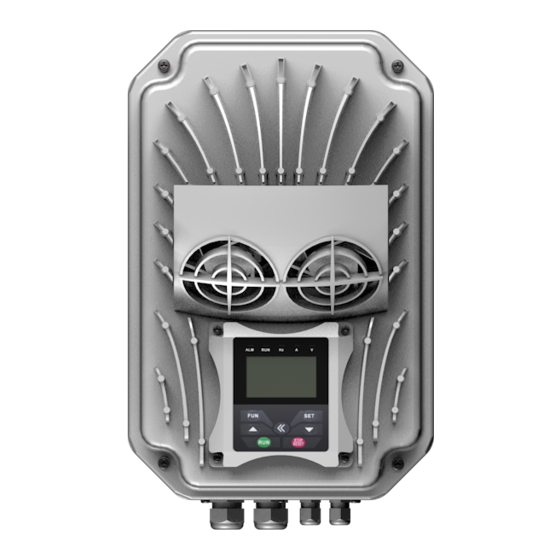
Installation Mode Support installing with motor 1.6 Appearance The external structure of EM30 series inverter: die-casting aluminum housing, anti-fingerprints fabrication processing, unique shape, high strength, good tenacity and convenience for maintenance. Taking EM30-0022T3J1 for instance, the external appearance and structure are shown as below in Fig1-2. -
Page 10: Designed Standards For Implementation
EM30 Exquisite structure design of aluminum casting housing, detachable cover structure and convenient connection can realize perfect combination with motor. Take EM30-0075T3J2 for instance, the external appearance and structure are shown as below in Fig1-3. Fig 1-3 Appearance and Structure 1.7 Designed Standards for Implementation IEC/EN 61800-5-1: 2007 Adjustable speed electrical power drive systems safety requirements. - Page 11 Meet the environmental requirements of EM30 series technical specifications in table 1-1. Before using the drive, the insulation of the motors must be checked, especially, if it is used for the first time or if it has been stored for a long time.
-
Page 12: Examination And Maintenance
EM30 Iout 100% ( m ) 1000 2000 3000 Fig 1-7 Derating Drive’s output current with altitude Fig 1-5 Derating drive‘s output current with altitude Never touch high-voltage terminals inside the inverter to avoid any electric shock. Before inverter is powered on, please be sure that input voltage is correct. ... -
Page 13: Keypad Panel
EM30 II. Keypad panel The keypad function and indicator function for EM30 series will be showed in panel operating illustration. Panel Illustration The panel covers three sections: data display section, status indicating section and keypad operating section, as shown in Fig. 2-1. -
Page 14: Panel Structure
EM30 2.2 Keypad panel and installation bracket structure 2.2.1 Structure Diagram 2.2.2 Structure Size (Unit: mm) Code Φ4.5 XX-X 2.2.3 Port of Control Panel Pins 8 core Reserved 5V GND 5V GND Signal 1 Signal 2 Signal 3 Signal 4 Note: The interface of control board should be completely consistent with the interface of the keypad panel, so the line sequence should also be the same. - Page 15 EM30 2.2.4 The remote-control components should reach the protection grade. The default remote-control wire length is 1m. The length of remote-control wire can be custom-made by users. If on the occasion of strong interference of occasion, or the length is longer than 3m, please put a magnetic ring on the wire to avoid interference.
-
Page 16: Panel Operating
EM30 2.3 Panel Operating All keys on the panel are available for user. Refer to Table 2-1 for their functions. Table 2-1 Uses of Keys Keys Names Remarks To call function code and switch over display mode. To call and save data. ▲... -
Page 17: Function Codes Switchover In/Between Code-Groups
EM30 Function Codes Switchover in/between Code-Groups It has more than 300 parameters (function codes) available to user, divided into 11 sections as indicated in Table 2-3. Table 2-3 Function Code Partition Group Group Group Name Group Name Timing control and protection Basic Parameters function Run Control Mode... -
Page 18: Operating Instructions Of 4-Line Lcd Interface Switch
EM30 Operating instructions of 4-line LCD interface switch 2.6.1 Operating instructions of SET/FUN keys Stop status Basic parameter 0.00 Keypad version: 1.01 Long press SET User password Current frequency Current frequency Press F100= 50.00 50.00 Stop status Press FUN to return Target frequency Target frequency Loosen SET... -
Page 19: Panel Display
EM30 2.6.3 Regulating target frequency/target rotate speed by UP/DOWN keys in running status Long press 0.00 50.00 1300 ▼ key Press Current frequency Current running frequency Target rotate speed Current status is current rotate speed 50.00 1500 1300 Loosen Target frequency Current rotate speed Current rotate speed ▼... -
Page 20: Installation & Connection
EM30 III. Installation & Connection Periphery Wiring Note: Braking unit is built in the T3 model of EM30 series, braking resistor is need only if the load inertia is not too large. · 16·... - Page 21 EM30 3.1.1 Accessories Graphic Illustration Brake unit adopts EURA standard, the rest shows as below table: Picture Name Description Device to transfer the electronic signals Cables Prevent from electric shock or protect the Breaker power supply and the cables system from over-current when short circuits occur.
-
Page 22: Installation
EM30 Installation The Figure below shows that the inverter is installed with motor: Fig 3-1 Sketch map of inverter installed with motor Note: Make sure effective ventilation space around drives. · 18·... -
Page 23: Connection
EM30 Connection Connect R/L1, S/L2 and T/L3 terminals (L1 and L2/N terminals for single-phase) with power source /PE/E to earth, U, V and W terminals to motor. from network, Motor must be ground connected. Or else electrified motor causes interference. Power terminals sketch of inverter with 1-phase 230V 0.4-2.2KW showed as below in Fig 3-2. - Page 24 EM30 Introduction of terminals of power loop Terminal Terminals Terminal Function Description Marking Power Input R/L1, S/L2, Input terminals of three-phase 400V AC voltage, 1-phase 230V Terminal T/L3 connects to L1, L2/N, 3-phase 230V connects to L1, L2/N and L3. Output Terminal U, V, W Inverter power output terminal, connected to motor.
-
Page 25: Function Of Control Terminals
EM30 3.4 Functions of control terminals The key to operate the inverter is to operate the control terminals correctly and flexibly. The control terminals are not operated separately, and they should match corresponding settings of parameters. This chapter describes basic functions of the control terminals. The users may operate the control terminals by combining relevant contents hereafter about ―Defined Functions of the Terminals‖. - Page 26 EM30 Self-contained Ground terminal of external control signal (voltage control signal or Analog Power supply current source control signal) is also the ground of 10V power supply of grounding Ground this inverter. RS485 differential Power RS-485 differential signal positive power supply signal positive supply Positive polarity...
- Page 27 EM30 If digital input control terminals are connected by drain electrode, please turn the toggle switch to the end of “PNP”. Wiring for control terminals as follows: Wiring for positive drain electrode (PNP mode) Inverter control board Wiring for active drain electrode (PNP mode) Inverter control board...
-
Page 28: Measurement Of Main Circuit
EM30 3.5 Measurement of main circuit(voltages, currents and powers) Since the voltages and currents on the inverter power supply and output sides include high-frequency components, measurement data depends on the instruments used and circuits measured. When commercial frequency instruments are used for measurement, measure the following circuits(Fig3-6) with the recommended instruments(Table 3-3). - Page 29 EM30 Table 3-3 Measuring instrucments Measuring Remarks (Reference Item Measuring Point Instrument Measurement Value) Power supply Moving-iron 380±15%, Across R-S,S-T, T-R voltage V1 type AC voltmeter 220V±15% Power supply Moving-iron R, S, and T line currents side current I1 type AC voltmeter Power supply At R, S and T, and across...
-
Page 30: Overall Connection
EM30 3.6 Overall Connection Refer to the figure below for overall connection sketch for EM30 series inverters. Wiring mode is available for various terminals whereas not every terminal needs connection when applied Braking resistor Braking unit Reactor 3-phase input AC 380V... -
Page 31: Solutions Of Conduction And Radiation Interference
EM30 3.7 Solutions of conductions and radiation interference The noise generated by the drive may disturb the equipment nearby. The degree of disturbance depends on the drive system, immunity of the equipment, wiring, installation clearance and earthing methods. 3.7.1 Noise propagation paths and suppressing methods ①... - Page 32 EM30 ③Basic methods of suppressing the noise Noise emission paths Actions to reduce the noise When the external equipment forms a loop with the drive, the equipment may suffer nuisance tripping due to the drive‘s earth leakage current. The problem can be solved ②...
- Page 33 EM30 3.7.3 Earthing Independent earthing poles (best) shared earthing pole (good) Other Other Drive Drive equipment equipment Shared earthing cable (not good) MCCB3 Power Switch Other Communication Interface Drive Freuency-conversion switch equipment MCCB1 Running automatically Linefrequency switch MCCB2 FR1-NC Running manually Frequency given Running automatically Pressure sensor...
- Page 34 EM30 Leakage current between lines The line leakage current flowing through the distribution capacitors of the drive out side may cause the thermal relay falsely activated, especially for the drive whose power is lower than 7.5kW. When the cable is longer than 50m, the ratio of leakage current to motor rated current may be increased that can cause the wrong action of external thermal relay very easily.
- Page 35 EM30 3.7.6 Application of Power Line Filter Power source filter should be used in the equipment that may generate strong EMI or the equipment that is sensitive to the external EMI. The power source filter should be a two-way low pass filter through which only 50Hz current can flow and high frequency current should be rejected.
-
Page 36: Operation And Simple Running
EM30 IV. Operation and Simple Running This chapter mainly introduces the basic knowledge of our products, related operation procedure and methods. It will be helpful to your correct operation. 4.1 Basic conception 4.1.1 Control mode EM30 inverter has three control modes: sensorless vector control (F106=0), VVVF control (F106=2) and vector control 1 (F106=6). -
Page 37: Keypad Panel And Operation Method
EM30 4.2 Keypad panel and operation method Keypad panel (keypad) is standard configuration of EM30 inverter. Through keypad panel, the user can carry out parameter setting, status monitoring and operation control over the inverter. Both keypad panel and display screen are arranged on the keypad controller, which mainly consists of three sections: data display section, status indicating section, and keypad operating section. - Page 38 EM30 4.2.3 Operation process of measuring motor parameters The user shall input the parameters accurately as indicated on the nameplate of the motor prior to selecting auto torque compensation of VVVF control mode. Inverter will match standard motor stator resistance parameters according to these parameters indicated on the nameplate.
- Page 39 EM30 4.2.4 Operation process of simple running Table 4-1 Brief Introduction to Inverter Operation Process Process Operation Reference Install the inverter at a location meeting the technical See Chapters I, II, specifications and requirements of the product. Mainly take into III.
-
Page 40: Illustration Of Basic Operation
EM30 After successful test run under no load, connect the load of drive system properly. Start the inverter with the keypad or control terminal, and increase the load gradually. When the load Checking under trail run is increased to 50% and 100%, keep the inverter run for a period respectively, to check if the system is running normally. - Page 41 EM30 4.3.1 Operation process of frequency setting, start, forward running and stop with keypad panel Connect the wires in accordance with Figure 4-1. After having checked the wiring successfully, switch on the air switch, and power on the inverter. Press the ―Fun‖ key, to enter the programming menu. Measure the parameters of the motor.
- Page 42 EM30 4.3.2 Operation process of setting the frequency with keypad panel, and starting, forward and reverse running, and stopping inverter through control terminals Connect the wires in accordance with Figure 4-2. After having checked the wiring successfully, switch on the air switch, and power on the inverter; 3-phase input AC 380V 50/60Hz...
- Page 43 F203 F208 There is a red four-digit coding switch SW1 near the control terminal block of EM30 series, as shown in Figure 4-4. The function of coding switch is to select the analog input terminals AI1and AI2, input range(0~5V/0~10V/0~20mA); In actual application, select the analog input channel through F203.
- Page 44 EM30 (11) There are two analog output terminals AO1 and AO2, both terminals can output voltage signal and current signal, the selecting switch of voltage/current is J5, the position of factory toggle switch is showed as below in Fig 4-5, AO1=V, AO2=I, the output relation is shown in table 4-3. Fig 4-5 Table 4-2 The Setting of Coding Switch and Parameters in the Mode of Analog Speed Control Set F203 to 1, to select channel AI1...
-
Page 45: Function Parameters
EM30 V. Function Parameters 5.1 Basic parameters User‘s Password Mfr‘s value: 0 F100 Setting range: 0~9999 ·When F107=1 with valid password, the user must enter correct user‘s password after power on or fault reset if you intend to change parameters. Otherwise, parameter setting will not be possible, and a prompt ―Err1‖ will be displayed. - Page 46 EM30 Setting range: Mfr‘s value: 0 F107 Password Valid or Not 0: invalid; 1: valid F108 Setting User‘s Password Mfr‘s value: 8 Setting range: 0~9999 · When F107 is set to 0, the function codes can be changed without inputting the password. When F107 is set to 1, the function codes can be changed only after inputting the user‘s password by F100.
- Page 47 EM30 Note: when speed track is working, acceleration/deceleration time, min frequency and target frequency are invalid. After speed track is finished, inverter will run to target frequency according to acceleration/deceleration time. Mfr‘s value: 50.00Hz F118 Corner Frequency (Hz) Setting range: 15.00~650.0 ·...
- Page 48 EM30 Mfr‘s value:0.00Hz F127/F129 Skip Frequency A,B (Hz) Setting range: 0.00~650.0 Mfr‘s value: 0.0 F128/F130 Skip Width A,B (Hz) Setting range:0~2.50 · Systematic vibration may occur when the motor is Output running at a certain frequency. This parameter is set Frequency (Hz)...
- Page 49 EM30 Setting range: 0: Frequency/function-code 2: Target rotary speed 4: PN voltage Mfr‘s value: 8: PID feedback value F132 Display items of stop 0+2+4=6 16: Temperature 32: Count value 64: PID given value 512: Setting torque Note: The setting and displaying of F132 is the same as F131. Mfr‘s value: 1.00 Setting range: 0.10~200.0 F133 Drive ratio of driven system...
- Page 50 EM30 To compensate low-frequency torque controlled by V(%) VVVF, output voltage of inverter while low-frequency should be compensated. When F137=0, linear compensation is chosen and it is applied on universal constant-torque load; When F137=1, square compensation is chose and it is applied on the loads of fan or water pump; When F137=2, user-defined multipoint compensation is chosen and it is applied on the special loads of spin-drier or centrifuge;...
- Page 51 EM30 As shown in Fig5-3, when F317=0, VF curve compensation =Max (F138, F141) When F137=1, VF curve compensation =Max (F139, F141) When F137=2, VF curve compensation =Max (Custom compensation, F141) When F317=3, auto compensation. F141 cannot be set too high; otherwise, inverter will easily trip into OH and OC. Multi-stage V/F curves are defined by 12 parameters from F140 to F151.
- Page 52 EM30 → Carrier-wave frequency High → Motor noise Loud → Waveform output Good → current Motor temperature High → Inverter temperature High → Leakage current High → Interference High Derating use is need if carrier frequency is adjusted to more than 10k. Refer to derating list below: Carrier Frequency Power 100%...
- Page 53 EM30 Setting range: Mfr‘s value: F159 Random carrier-wave selection 0: Control speed normally(prohibited) 1: Random carrier-wave frequency(allowed) When F159=0, inverter will modulate as per the carrier-wave set by F153. When F159=1, inverter will operate in mode of random carrier-wave modulating. Note: when random carrier-wave is selected, output torque will increase but noise will be loud.
-
Page 54: Operation Control
EM30 5.2 Operation Control Setting range: 0: Keypad command; 1: Terminal command; Mfr‘s value: 4 F200 Source of start command 2: Keypad+Terminal; 3: MODBUS; 4: Keypad+Terminal+MODBUS Setting range: 0: Keypad command; 1: Terminal command; Mfr‘s value: 4 F201 Source of stop command 2: Keypad+Terminal;... - Page 55 EM30 Setting range: 0: Memory of digital given; 1: External analog AI1; 2: External analog AI2; 3: Pulse input given; Mfr‘s value: 0 F203 Main frequency source X 4: Stage speed control; 5: No memory of digital given; 7, 8:Reserved; 9: PID adjusting;...
- Page 56 EM30 Setting range: 0: Memory of digital given; 1: External analog AI1; F204 Accessorial frequency Mfr‘s value: 0 2: External analog AI2; source Y 3: Pulse input given; 4: Stage speed control; 5: PID adjusting; · When accessorial frequency Y is given to channel as independent frequency, it has the same function with main frequency source X.
- Page 57 EM30 Setting range: F205 reference for selecting accessorial Mfr‘s value: 0 0: Relative to max frequency; frequency source Y range 1: Relative to main frequency X Mfr‘s value: 100 F206 Accessorial frequency Y range (%) Setting range: 0~100 · When combined speed control is adopted for frequency source, F206 and F205 are used to confirm the relative object of the setting range for the accessorial frequency.
- Page 58 EM30 Frequency given mode can be switched over by selecting F207. For example: switching PID adjusting and normal speed control, switching stage speed and analog given, switching PID adjusting and analog given, and so on. The acceleration/deceleration time of stage speed is set by function code of corresponding stage speed time.
- Page 59 EM30 Two-line operation mode 2: when this mode is used, FWD is enable terminal, the direction is controlled by REV terminal. For example: ―FWD‖ terminal-----―open‖: stop, ―closed‖: running; ―REV‖ terminal-----―open‖: forward running, ―closed‖: reverse running; ―CM‖ terminal-----common port Running command Stop Stop Forward running...
- Page 60 EM30 Setting range: 0: stop by deceleration time; Mfr‘s value: 0 F209 Selecting the mode of stopping the motor 1: free stop 2: DC braking stop When the stop signal is input, stopping mode is set by this function code: F209=0: stop by deceleration time Inverter will decrease output frequency according to setting acceleration/deceleration curve and decelerating time, after frequency decreases to 0, inverter will stop.
- Page 61 EM30 Mfr‘s value: 60.0 F215 Auto-starting delay time Setting range: 0.1~3000.0 F215 is the auto-starting delay time for F213 and F214. The range is from 0.1s to 3000.0s. F216 Times of auto-starting in case of Mfr‘s value: 0 Setting range: 0~5 repeated faults Mfr‘s value: 3.0 F217 Delay time for fault reset...
-
Page 62: Multifunctional Input And Output Terminals
EM30 5.3 Multifunctional Input and Output Terminals 5.3.1 Digital multifunctional output terminals Mfr‘s value: 1 F300 Relay token output Setting range: 0~45 Mfr‘s value: 14 F301 DO1 token output Refer to table 5-2 for detailed instructions. Mfr‘s value: 5 F302 DO2 token output F300~F302 are still valid when rotate speed tracking. - Page 63 EM30 Analog line Indicating inverter detects analog input lines disconnection, and ON signal is output. Please refer to F741. disconnection protection Under-load 1 pre-alarm Please refer to FA26 and FA27. When inverter output current has fallen to zero current detecting Zero current detecting value and after the setting time of F755, ON signal is output.
- Page 64 EM30 Please refer to Fig 5-9 about S curve acceleration/deceleration: Target Fre ③ ③ ② ② Time ① ① Fig 5-9 S Curve Acceleration /Deceleration T1 is the acceleration time from present frequency to target frequency. T2 is the deceleration time from present frequency to target frequency. During the acceleration process, in the ①...
- Page 65 EM30 F313 Count frequency divisions Setting range:1~65000 Mfr‘s value: 1 F314 Set count value Setting range: F315~65000 Mfr‘s value: 1000 F315 Designated count value Setting range: 1~F314 Mfr‘s value : 500 Count frequency divisions refer to the ratio of actual pulse input and inverter‘s count times, i.e., Actual Pulse Input Inverter‘s Count Times =...
- Page 66 EM30 5.3.2 Digital multifunctional input terminals Setting range: 0: No function; 1: Running ; Mfr‘s value: 11 F316 DI1 terminal function setting 2: Halt; 3: Multi-stage speed 1; 4: Multi-stage speed 2; 5: Multi-stage speed 3; 6: Multi-stage speed 4; 7: Reset;...
- Page 67 EM30 Table 5-3 Instructions for digital multifunctional input terminal Value Function Instructions Even if signal is input, inverter will not work. This function can be No function set by undefined terminal to prevent mistake action. When running command is given by terminal or terminals Running terminal combination and this terminal is valid, inverter will run.
- Page 68 EM30 When PID control, FA26=1, corresponding terminal has signal, the Water signal inverter will relieve water shortage protection state When PID control is valid and this terminal is valid, the setting Fire pressure switchover value of PID switches into fire pressure given (FA58). When emergency fire mode (FA59) is valid, inverter will be in Emergency fire control emergency fire mode.
- Page 69 EM30 Fig 5-11 PTC protection sketch map User can follow the followings operations if using PTC as thermal protection. When the coding switch is in the ―NPN‖ side and terminal is set as 38, PTC resistor should be connected between CM and DIx terminal. When the coding switch is in ―PNP‖...
- Page 70 EM30 Note: K4 is multi-stage speed terminal 4, K3 is multi-stage speed terminal 3, K2 is multi-stage speed terminal 2, K1 is multi-stage speed terminal 1. And 0 stands for OFF, 1 stands for ON. 0=OFF, 1=ON The setting of this table is valid when F580=0. Setting range: Mfr‘s value: 0 F324 Free stop terminal logic...
- Page 71 EM30 If user wants to see the detailed status for each terminal, set the function code as F330, press ―SET‖ to enter diagnosis interface, which is showed below. DIG IN 0000 0000 000% 000% The first line indicates digital input, digital output; First six boxes in the second line indicate the state of DI terminals, terminals from left to right are DI1~DI6, solid-line box is the state showed as above when terminal is invalid;...
-
Page 72: Analog Input And Output
If user wants to set both DI1 and DI4 to negative logic, please set F340=1+8=9 and the like. 5.4 Analog Input and Output EM30 series inverters have 2 analog input channels and 2 analog output channels. Mfr‘s value: 0.04 F400 Lower limit of AI1 channel input (V) Setting range: 0.00~F402... - Page 73 0Hz. If the voltage is in this range, inverter will output 0Hz. 0Hz voltage dead zone will be valid when corresponding setting for lower limit of input is less than 1.00. AO1, AO2 are provided as two analog output channels for EM30 series. · 69·...
- Page 74 EM30 0: 0~5V; Mfr‘s value: 1 F423 AO1 output range 1: 0~10V or 0~20mA 2: 4~20mA Mfr‘s value: 0.05 F424 AO1 lowest corresponding frequency (Hz) Setting range: 0.0~F425 Mfr‘s value: 50.00 F425 AO1 highest corresponding frequency (Hz) Setting range: F424~F111 Mfr‘s value: 100 F426 AO1 output compensation (%) Setting range: 0~120...
-
Page 75: Pulse Input And Output Control
EM30 5.5 Pulse Input and Output Control Mfr‘s value: 0.00 F440 Min frequency of input pulse FI (KHz) Setting range: 0.00~F442 Mfr‘s value: 1.00 F441 Corresponding setting of FI min frequency Setting range:0.00~F443 Mfr‘s value: 10.00 F442 Max frequency of input pulse FI (KHz) Setting range: F440~100.00 Setting range: Mfr‘s value: 2.00... - Page 76 EM30 The unit of corresponding setting for max/min input pulse frequency is in percentage (%). If the value is greater than 1.00, it is positive; if the value is less than 1.00, it is negative. (e.g. F441=0.5 represents –50%).The corresponding setting benchmark: in the mode of combined speed control, pulse input is the accessorial frequency and the setting benchmark for range of accessorial frequency which relatives to main frequency (F205=1) is ―main...
- Page 77 EM30 Setting range: F460 AI1channel input mode 0: straight line mode Mfr‘s value: 0 1: folding line mode Setting range: F461 AI2 channel input mode Mfr‘s value: 0 0: straight line mode 1: folding line mode F462 AI1 insertion point A1 voltage value (V) Setting range: F400~F464 Mfr‘s value: 2.00 F463 AI1 insertion point A1 setting value...
-
Page 78: Multi-Stage Speed Control
The function of multi-stage speed control is equivalent to a built-in PLC in the inverter. This function can set running time, running direction and running frequency. EM30 series inverter can realize 15-stage speed control and 8-stage speed auto circulating. During the process of speed track, multi-stage speed control is invalid. After speed track is finished, inverter will run to target frequency according to the setting value of parameters. - Page 79 EM30 · If F503=0, then inverter will stop after auto circulation is finished. If F503=1, then inverter will run at the speed of the last-stage after auto-circulation is finished as follows: e.g., F501=3, then inverter will run at auto circulation of 3-stage speed; F502=100, then inverter will run 100 times of auto circulation;...
- Page 80 EM30 F573~F579 Setting range: Mfr‘s value: 0 Running directions of stage speeds from stage 9 to 0: forward running; stage 15 (S) 1: reverse running F557 ~ 564 Running time of stage speeds from Setting range: Mfr‘s value: 1.0 Stage 1 to Stage 8 (S) 0.1~3000 F565~F572 Stop time after finishing stages from...
-
Page 81: Auxiliary Functions
EM30 5.7 Auxiliary Functions Setting range: 0: Invalid; Mfr‘s value: 0 1: braking before starting; F600 DC Braking Function Selection 2: braking during stopping; 3: braking during starting and stopping Mfr‘s value: 1.00 F601 Initial Frequency for DC Braking (Hz) Setting range: 0.20~50.00 F602 DC Braking efficiency before Starting Mfr‘s value: 10 Setting range: 0~100... - Page 82 EM30 Setting range: 0~2:Reserved Mfr‘s value: 3 F607 Selection of Stalling Adjusting Function 3: Voltage/current control 4: Voltage control 5: Current control Mfr‘s value: 160 F608 Stalling Current Adjusting (%) Setting range: 60~FC49 Mfr‘s value: F609 Stalling Voltage Adjusting (%) Setting range: 110~200 1-phase 220V: 130 3-phase 380V: 140...
- Page 83 EM30 Setting range: 0: invalid F613 Speed track Mfr‘s value: 0 1: valid 2: valid at the first time When F613=0, the function of speed track is invalid. When F613=1, the function of speed track is valid. After inverter tracks motor speed and rotating direction, inverter will begin running according to the tracked frequency, to start the rotating motor smoothly.
- Page 84 EM30 The related fault in the process of parameters copy is in the table below: Code Causes Er71 Copy timeout During copying process, there is no valid data after 3s. Er72 Copy when running Parameters copy when inverter is in the running status. Er73 Copy without input password Password is valid and user does not input password.
- Page 85 EM30 Running frequency Rotation speed Target speed Output current Output voltage DC bus voltage PID setting value PID feedback value Radiator temperature Count value Linear speed Channel for main frequency Main frequency Channel for accessorial frequency Accessorial frequency Output torque Setting torque F645 Status...
- Page 86 EM30 Setting range: 0: Invalid Mfr‘s value: 0 F657 Instantaneous power failure selection 1: Reduce frequency 2: slow down to stop Setting range: 0.0~3000s Mfr‘s value: 0.0 F658 Voltage rally acceleration time 0.0: F114 Setting range: 0.0~3000s Mfr‘s value: 0.0 F659 Voltage rally deceleration time 0.0: F115 F660 Action judging voltage at instantaneous...
- Page 87 EM30 F670 Voltage-limit current-limit adjustment coefficient Setting range: 0.01~10.00 Mfr‘s value: 2.00 Lower this factor properly if frequent over-voltage protection occurs in the process of deceleration; Increase the factor when deceleration is too slow. Setting range: 0: F672 1: AI1 2: AI2 Mfr‘s value: 0 F671 voltage source for V/F separation...
-
Page 88: Malfunction And Protection
EM30 5.8 Malfunction and Protection Setting range: Mfr‘s value: 0 0: free stop immediately; F700 Selection of terminal free stop mode 1: delayed free stop F701 Delay time for free stop and programmable Mfr‘s value: 0.0 Setting range: 0.0~60.0S terminal action ·... - Page 89 EM30 When the output frequency is lower than 10Hz, the heat dissipation effect of common motor will be worse. So when running frequency is lower than 10Hz, the threshold of motor overload value will be reduced. Please refer to Fig 5-20 (F707=100%): Time (minutes) <5Hz 5~10Hz >10Hz...
- Page 90 EM30 Setting range: F725 Under-voltage protection 1: reset manually Mfr‘s value: 2 2: reset automatically Setting range: Mfr‘s value: 1 F726 Overheat 0: invalid; 1: valid Setting range: Mfr‘s value: 1 F727 Output phase loss 0: invalid; 1: valid Mfr‘s value: 5 F728 Input phase loss filtering constant (S) Setting range: 1~60 Mfr‘s value: 5...
- Page 91 EM30 When F747=1, the temperature of radiator reaches certain temperature, inverter carrier frequency will adjust automatically, to decrease the temperature of inverter. This function can avoid overheat malfunction. When F159=1, random carrier frequency is selected, F747 is invalid. When F106=6, F747 is invalid all the time when selecting PMSM sensorless vector control. Mfr‘s value: 1.0 F752 Overload quitting coefficient Setting range: 0.1~20.0...
-
Page 92: Parameters Of The Motor
EM30 5.9 Parameters of the Motor Setting range: 0: Invalid; F800 Motor‘s parameters tuning Mfr‘s value: 0 1: Rotating tuning; 2: stationary tuning F801 Rated power (kW) Setting range: 0.1~1000 Subject to model F802 Rated voltage (V) Setting range: 1~1300 F803 Rated current (A) Setting range: 0.2~6553.5 F804 Number of motor poles... - Page 93 EM30 3. Incorrect parameters of the motor may result in unstable running of the motor or even failure of normal running. Correct tuning of the parameters is a fundamental guarantee of vector control performance. Each time when F801 rated power of the motor is changed, the parameters of the motor (F806-F809) will be refreshed to default settings automatically.
- Page 94 EM30 F815 F814 F813 F816 F817 F818 F817 F818 Fig 5-21 PID parameter Dynamic response of vector control speed can be adjusted through adjusting proportional and storage gains of speed loop. Increasing KP and KI can speed up dynamic response of speed loop. However, if proportional gain or storage gain is too large, it may give rise to oscillation.
- Page 95 EM30 F870 PMSM back electromotive Setting range: 0.1~999.9 Mfr‘s value: 100.0 force (mV/rpm) (valid value between lines) F871 PMSM D-axis inductance (mH) Setting range: 0.01~655.30 Mfr‘s value:5.00 F872 PMSM Q-axis inductance (mH) Setting range: 0.01~655.30 Mfr‘s value:7.00 Setting range: 0.001~65.535 F873 PMSM stator resistance(Ω)...
-
Page 96: Communication Parameters
EM30 5.10 Communication Parameter Setting range: F900 Communication Address 1~255: single inverter address Mfr‘s value: 1 0: broadcast address Setting range: 1: ASCII F901 Communication Mode Mfr‘s value: 2 2: RTU 3: Remote Keypad F902 Stop bits Setting range: 1~2 Mfr‘s value: 2 Setting range: F903 Parity Check... -
Page 97: Pid Parameters
EM30 5.11 PID Parameters 5.11.1 Internal PID adjusting and constant pressure water supply Internal PID adjusting control is used for single pump or double pump automatic constant-pressure water supply, or used for simple close-loop system with convenient operation. The usage of pressure meter: As FAO2=1: channel AI1 ―10V‖... - Page 98 EM30 Mfr‘s value:100.0 FA03 Max limit of PID adjusting (%) FA04~100.0 Mfr‘s value:50.0 FA04 Digital setting value of PID adjusting (%) FA05~FA03 Mfr‘s value:0.0 FA05 Min limit of PID adjusting (%) 0.0~FA04 When negative feedback adjusting is valid, if pressure is higher than max limit of PID adjusting, pressure protection will occur.
- Page 99 EM30 FA22 is set as PID adjustor sampling period, which means that the sampling time to feedback value for PID adjustor. The shorter the sampling time is, the faster adjustment speed is. Its basic unit is 2ms. E.g. 1 means sampling period is 2ms;...
- Page 100 EM30 When starting general pump or interchange time is over, inverter will free stop. After starting general pump, inverter will delay the set time of FA30, and restart converter pump. When inverter drives two pumps and negative feedback adjusting, if the frequency already reach the max value and after the delay time (FA31), the pressure value is still lower than the value, then the inverter will stop output immediately and motor will freely stop.
-
Page 101: Torque Control Parameters
EM30 5.12 Torque control parameters Setting range: 0:Speed control FC00 Speed/torque control selection Mfr‘s value: 0 1:Torque control 2:Terminal switchover 0: speed control. Inverter will run by setting frequency, and output torque will automatically match with the torque of load, and output torque is limited by max torque (set by manufacture.) 1: Torque control. - Page 102 EM30 Setting range: 0: Digital given (FC23) 1: Analog input AI1 FC22 Forward speed limited channel 2: Analog input AI2 4: Pulse input channel FI 5: Reserved FC23 Forward speed limited (%) 0~100.0 10.0 0: Digital given (FC25) 1: Analog input AI1 FC24 Reverse speed limited channel 2: Analog input AI2...
-
Page 103: Parameters Display
EM30 Current or torque F 608/FC30 FC49 FC50 FC51 5.13 Parameters Display H000 Running frequency/target frequency(Hz) In stopped status, target frequency is displayed. In running status, running frequency is displayed. H001 Actual speed/target speed (rpm) In stopped status, actual speed is displayed. In running status, target speed is displayed. H002 Output current (A) In running status, output current is displayed. - Page 104 EM30 H017 Current stage speed for multi-stage speed In multi-stage speed mode, current stage speed is displayed by H017. H018 Frequency of input pulse Input pulse frequency of DI1 terminal is displayed by H018, the unit is 0.01 H019 Feedback speed (Hz) Feedback speed is displayed as frequency by H019.
-
Page 105: Maintenance
EM30 VI. Maintenance Because the potential malfunctions may be caused by the influence of environmental temperature, humidity, dust and vibration, or aging and wearing components of internal inverter, daily inspection and periodic maintenance are necessary for inverter. Be aware that check the content below to avoid electric shock hazard before inspection and maintenance: The inverter‘s power is shut off. -
Page 106: Exchange Of Vulnerable Parts
EM30 6. At least one time power-on test must proceed within 2 years for Inverters of long-term storage. Use voltage regulator to raise rated value gradually, which during time is around 5 hours without load. 7. For the insulation test to inverter, grounding test must proceed after shorting all the input/output terminals (L1/R, L2/S, L3/T, U, V, W, PE, P/+, N/- and B/BR) of main loop with wires. -
Page 107: Motor
EM30 VII. Motor 7.1. Motor Nameplate 7.1.1. Nameplate of EVPM motor 7.1.2. Nameplate of EVIM motor · 103·... -
Page 108: Naming Rule
EM30 7.2. Naming Rule 7.2.1. EVPM Motor Naming Rule: EVPM - 751 I N 4 Y071 D 15 S A 03 Installation mode Design code Motor Rotation Speed 15: 1500rpm 18: 1800rpm 30: 3000rpm 36: 3600rpm 45: 4500rpm Axle stretch C: Axis without keyway and with C hole D: Axis with keyway and C... - Page 109 EM30 7.2.2. EVIM Motor Naming Rule EVIM - 751 S N 4 Y071 D 15 S S 03 Installation mode: 03: IBM3 05: IBM5 14: IBM14 35:IBM35 Design code Motor Rotation Speed: 10: 1000rpm 15: 1500rpm 30: 3000rpm Axle stretch C : Axis without keyway and with C hole D : Axis with keyway and C...
-
Page 110: Motor Technical Specification
EM30 7.3. Motor Technical Specification Table 7-1 EVPM motor technical specification Motor Model PM Motor(Permanent-magnet) Magnetic material Highest intrinsic coercivity rare earth permanent materials Motor Power 0.75~7.5KW 0.4~2.2KW Rated voltage 400V 230V Rotor magnet steel Interior (Significant difference for inductance of DQ axis) Magnetic steel Demagnetization temperature≥130℃... -
Page 111: Motor Type
EM30 7.4. Motor Type 7.4.1. EVPM motor type list Rotate Rated Momentary Pole Rated Torque Motor Model Speed Current Overload (Nm) (rpm) (A) Capacity(Nm) 1500 EVPM-751IN4Y071D15A** 1500 EVPM-112IN4Y071D15A** 2.45 EVPM-152IN4Y090D15A** 1500 19.2 EVPM-222IN4Y090D15A** 1500 EVPM-302IN4Y090D15A** 1500 19.1 38.2 EVPM-402IN4Y112D15A** 1500 25.5 51.2 EVPM-552IN4Y112D15A**... - Page 112 EM30 EVPM-201IN4Y063D15A03 1500 1.27 2.54 EVPM-401IN4Y063D15A03 1500 2.54 5.08 1500 EVPM-401IN2Y063D15A03 2.54 5.08 1500 EVPM-751IN2Y071D15A03 1500 EVPM-112IN2Y071D15A03 1500 EVPM-152IN2Y090D15A03 19.2 1500 EVPM-222IN2Y090D15A03 3000 EVPM-401IN2Y063D30A03 1.27 2.54 3000 EVPM-751IN2Y071D30A03 3000 EVPM-112IN2Y071D30A03 3000 EVPM-152IN2Y090D30A03 3000 EVPM-222IN2Y090D30A03 7.4.2. EVIM motor type list Rated Rated Rated Pole...
- Page 113 EM30 EVIM-751SN4Y080D15A03 1500 1.88 EVIM-112SN4Y090D15A03 1500 2.53 EVIM-152SN4Y090D15A03 1500 10.1 EVIM-222SN4Y100D15A03 1500 14.6 EVIM-302SN4Y100D15A03 1500 19.8 EVIM-402SN4Y112D15A03 1500 26.5 EVIM-552SN4Y132D15A03 1500 11.3 36.2 EVIM-752SN4Y132D15A03 1500 14.9 49.2 EVIM-113SN4Y160D15A03 1500 21.9 71.7 EVIM-153SN4Y160D15A03 1500 29.3 97.8 EVIM-183SN4Y180D15A03 1500 35.4 120.2 EVIM-223SN4Y180D15A03 1500 41.9 142.4...
-
Page 114: Reference Table Of Inverter And Motor
EM30 7.5. Reference Table of inverter and motor 7.5.1. Reference Table of inverter and EVPM motor Power (KW) EM30 Inverter Model EVPM Motor Model EVPM-751IN2Y071D15A03 EM30-0007S2J1U1F2 (AC01/2)(B1)(R3)M1 0.75 EVPM-751IN2Y071D30A03 EVPM-152IN2Y090D30A03 EM30-0015S2J1U1F2 (AC01/2)(B1)(R3)M1 EVPM-152IN2Y090D15A03 EVPM-222IN2Y090D30A03 EM30-0022S2J1U1F2 (AC01/2)(B1)(R3)M1 EVPM-222IN2Y090D15A03 EVPM-751IN4/3Y071D30A03 EM30-0007T3J1U1F2 (AC01/2)(B1)(R3)M1 0.75 EVPM-751IN4/3Y071D15A03 EVPM-152IN4/3Y090D30A03... -
Page 115: Motor Installation Size
EM30 EVIM-152SN4/3Y090D30A03 EM30-0015T3J1U1F2(AC01/2)(B1)(R3)M2 EVIM-152SN4/3Y090D15A03 EVIM-152SN4/3Y100D10A03 EVIM-222SN4/3Y090D30A03 EM30-0022T3J1U1F2(AC01/2)(B1)(R3)M2 EVIM-222SN4/3Y100D15A03 EVIM-222SN4/3Y112D10A03 EVIM-302SN4/3Y100D30A03 EM30-0030T3J1U1F2(AC01/2)(B1)(R3)M2 EVIM-302SN4/3Y100D15A03 EVIM-302SN4/3Y132D10A03 EVIM-402SN4/3Y112D30A03 EM30-0040T3J1U1F2(AC01/2)(B1)(R3)M2 EVIM-402SN4/3Y112D15A03 EVIM-402SN4/3Y132D10A03 EVIM-552SN4/3Y132D30A03 EM30-0055T3J1U1F2(AC01/2)(B1)(R3)M2 EVIM-552SN4/3Y132D15A03 EVIM-552SN4/3Y132D10A03 EVIM-752SN4/3Y132D30A03 EM30-0075T3J1U1F2(AC01/2)(B1)(R3)M2 EVIM-752SN4/3Y132D15A03 EVIM-752SN4/3Y160D10A03 7.6. Motor Installation Size 7.6.1. EM30 Installation Size · 111·... - Page 116 EM30 EM30 overall dimensions Model Frame EM30-0004S2J1U1F2(AC01/2)(B1)(R3)M1 EM30-0007S2J1U1F2(AC01/2)(B1)(R3)M1 EM30-0015S2J1U1F2(AC01/2)(B1)(R3)M1 62.5 EM30-0022S2J1U1F2(AC01/2)(B1)(R3)M1 62.5 EM30-0007T3J1U1F2(AC01/2)(B1)(R3)M1 62.5 EM30-0015T3J1U1F2(AC01/2)(B1)(R3)M1 62.5 EM30-0022T3J1U1F2(AC01/2)(B1)(R3)M1 62.5 EM30-0030T3J1U1F2(AC01/2)(B1)(R3)M1 100L EM30-0040T3J2U1F2(AC01/2)(B1)(R3)M1 132S EM30-0055T3J2U1F2(AC01/2)(B1)(R3)M1 132M 132S EM30-0075T3J2U1F2(AC01/2)(B1)(R3)M1 132M EM30-0007S2J1U1F2(AC01/2)(B1)(R3)M2 62.5 EM30-0015S2J1U1F2(AC01/2)(B1)(R3)M2 62.5 EM30-0022S2J1U1F2(AC01/2)(B1)(R3)M2 62.5 EM30-0007T3J1U1F2(AC01/2)(B1)(R3)M2 62.5 EM30-0015T3J1U1F2(AC01/2)(B1)(R3)M2 62.5 EM30-0022T3J1U1F2(AC01/2)(B1)(R3)M2 62.5 EM30-0030T3J1U1F2(AC01/2)(B1)(R3)M2 100L EM30-0040T3J2U1F2(AC01/2)(B1)(R3)M2 132S...
-
Page 117: Installation
EM30 7.7. Installation Check the information of nameplate is satisfy with requirement, Check carefully before installation: If motor has bump or deformation and fasteners have loose or dislocation during transport. Motor shaft cannot be dragged when transferring. Use spring cushion to fasten when fixing the motor. Try the best to avoid the vibration of bearing block. - Page 118 EM30 7.8.2. Motor winding short-circuit Short-circuit to ground in winding Shut down motor immediately and fix if there is obvious noise with aggravated vibration and overheat when operation. It is because the damage of winding insulation, the wire of winding is collide with shell or core, which makes short-circuit to ground in winding.
-
Page 119: Maintenance & Servicing
EM30 7.8.4. Motor overheat failure cause, phenomena and treatment Cause and phenomena Treatment Mismatching of power. Change high-power motor. Phase-broken of motor, high current caused Check and eliminate motor failure. by short-circuit in winding or over-current Check if there is foreign matter between protection of invertor. -
Page 120: Appendix 1 Trouble Shooting
EM30 Appendix 1 Trouble Shooting When malfunction occurs to inverter, don‘t run by resetting immediately. Check any causes and get it removed if there is any. Take counter measures by referring to this manual in case of any malfunctions on inverter. Should it still be unsolved, contact the manufacturer. - Page 121 EM30 *check if control board is connected Current malfunction *Current alarm signal exists before 12: Err3 with power board well. before running running. *ask for help from manufacture. Parameters tuning *Do not connect motor when 13: Err2 *please connect motor correctly. wrong measuring parameters Current zero...
- Page 122 EM30 Table 1-2 Motor Malfunction and Counter Measures Malfunction Items to Be Checked Counter Measures Wiring correct? Get connected with power Setting correct? Check wiring; Motor not Running Too big with load? Checking malfunction; Motor is damaged? Reduce load; Malfunction protection occurs? Check Table 1-1 Wrong Direction of U, V, W wiring correct?
-
Page 123: Appendix 2 Reference Wiring Of Water System
EM30 Appendix 2 Reference Wiring of water system 1. Fixed mode of 1 inverter driving 2 pumps MCCB3 Power Switch Communication Interface Freuency-conversion switch MCCB1 Running automatically Linefrequency switch MCCB2 FR1-NC Running manually Frequency given Running automatically Pressure sensor FR2-NC Running manually Please connect the wiring according to above wiring, after checking the wiring and close MCCB3. - Page 124 EM30 2. Rotating mode of 1 inverter driving 2 pumps MCCB3 Power switch Communication interface MCCB1 Frequency-conversion switch Run automatically Linefrequency switch MCCB2 FR1-NC Run manually Frequency given Run automatically +24V Pressure sensor FR2-NC Run manually Please connect the wiring according to above wiring, after checking the wiring and close MCCB3. Please set F208=1, F203=9, FA00=2, FA36=1, FA37=1, FA47=1, FA48=2, FA04=pressure percentage, FA03=channel limit pressure, and FA05 In manual status, please close power-frequency switch MCCB2.
-
Page 125: Appendix 3 Products And Structure
Products & Structures EM30 series inverter has its power range between 0.4~7.5kW. Refer to Tables 3-1 and 3-2 for main data. There may be two (or more than two) kinds of structures for certain products. Please make a clear indication when placing your order. - Page 126 EM30 J1 Structure J2 Structure · 122·...
-
Page 127: Appendix 4 Selection Of Braking Resistance
EM30 Appendix 4 Selection of Braking Resistance Inverter model Applicable motor Min resistor value (Ω) Min resistor power power (kW) EM30-0004S2 EM30-0007S2 0.75 200W EM30-0015S2 EM30-0022S2 EM30-0007T3 0.75 100W EM30-0015T3 150W EM30-0022T3 250W EM30-0030T3 250W EM30-0040T3 400W EM30-0055T3 550W EM30-0075T3 750W Note: in the occasion of large inertia load, if the braking resistor heat is serious, please adopt the larger power of resistor than recommended resistor. -
Page 128: Appendix 5 Communication Manual
ASCII Code 2.1.3 RTU Mode In RTU mode, one Byte is expressed by hexadecimal format. For example, 31H is delivered to data packet. 2.2 Baud rate Setting range of EM30 series: 1200, 2400, 4800, 9600, 19200, 38400, 57600 · 124·... - Page 129 EM30 2.3 Frame structure: ASCII mode Byte Function Start Bit (Low Level) Data Bit Parity Check Bit (None for this bit in case of no checking. Otherwise 1 bit) Stop Bit (1 bit in case of checking, otherwise 2 bits) RTU mode Byte Function...
- Page 130 EM30 2.4.3 Protocol Converter It is easy to turn a RTU command into an ASCII command followed by the lists: Use the LRC replacing the CRC. Transform each byte in RTU command into a corresponding two byte ASCII. For example: transform 0x03 into 0x30, 0x33 (ASCII code for 0 and ASCII code for 3).
- Page 131 EM30 2.5.2.2 Running status parameters Parameters Address Parameter Description(read only) 1000 Output frequency 1001 Output voltage 1002 Output current 1003 Pole numbers/ control mode, high-order byte is pole numbers, low-order byte is control mode. 1004 Bus-line voltage Drive ratio/inverter status High-order byte is drive ratio, low-order byte is inverter status Inverter status: 0X00: Standby mode...
- Page 132 EM30 1100 : stage speed 12 1101 : stage speed 13 1110 : stage speed 14 1111 : stage speed 15 1014 Monitoring external counting value Monitoring analog output percent, AO1 (0~100.00) 1015 Monitoring analog output percent, AO2 (0~100.00) 1016 1017 Monitoring current speed.
- Page 133 EM30 2.5.2.2.3 Illegal Response When Reading Parameters Command Description Function Data Command meaning: 0001: Illegal function code Slave parameters response The highest-order byte changes into 1. 0002: Illegal address 0003: Illegal data note 2 0004: Slave fault Note 2: Illegal response 0004 appears below two cases: Do not reset inverter when inverter is in the malfunction state.
- Page 134 Inverter Connecting Diagram of Field Bus RS485 Half-duplex communication mode is adopted for EM30 series inverter. Daisy chain structure is adopted by 485 Bus-line. Do not use 'spur' lines or a star configuration. Reflect signals which are produced by spur lines or star configuration will interfere in 485 communications.
- Page 135 EM30 Grounding and Terminal Terminal resistance of 120 ohm will be adopted for terminal of RS485 network, to diminish the reflection of signals. Terminal resistance shall not be used for intermediate network. No direct grounding shall be allowed for any point of RS485 network. All the equipment in the network shall be well grounded via their own grounding terminal.
- Page 136 EM30 Eg 2:Read output frequency, output voltage, output current and current rotate speed from N0.2 inverter. Host Query First First Register Register Address Function Register Register count Hi count L0 Address Hi Address Lo Communication Parameters Address 1000H Slave Response: Output Frequency Output Voltage Output Current...
- Page 137 EM30 Eg4: Read the value of F113, F114 from NO.2 inverter Host Query: Register Register Register Register Address Function Address Hi Address Lo Count Hi Count L0 Communication Parameter Address F10DH Numbers of Read Registers Slave Normal Response The first The first The second The second...
-
Page 138: Appendix 6 Zoom Table Of Function Code
EM30 Appendix 6 Zoom Table of Function Code Basic parameters: F100-F160 Function Chan Mfr‟s Value Function Definition Setting Range Code User‘s Password √ F100 0~9999 Inverter‘s Rated Current (A) △ F102 Subject to inverter model △ F103 Inverter Power (kW) Subject to inverter model F104 Reserved... - Page 139 EM30 √ F127 Skip Frequency A 0.00~650.0Hz 0.00 √ F128 Skip Width A 0.00~2.50Hz 0.00 √ F129 Skip Frequency B 0.00~650.0Hz 0.00 √ F130 Skip Width B 0.00~2.50Hz 0.00 0-Present output frequency / function code 1 - Current output rotary speed 2-Output current 4-Output voltage...
- Page 140 EM30 User-defined voltage point ╳ F143 0~100 2(%) User-defined frequency ╳ F144 F142~F146 10.00 point 3 (Hz) User-defined voltage point ╳ F145 0~100 3(%) User-defined frequency ╳ F146 F144~F148 20.00 point 4 (Hz) User-defined voltage point ╳ F147 0~100 4(%) User-defined frequency ╳...
- Page 141 EM30 Running control mode: F200-F230 0: Keypad command; 1: Terminal command; ╳ 2: Keypad+Terminal; F200 Source of start command 3:MODBUS; 4: Keypad+Terminal+MODBUS 0: Keypad command; 1: Terminal command; ╳ 2: Keypad+Terminal; F201 Source of stop command 3:MODBUS; 4: Keypad+Terminal+MODBUS 0: Forward running locking; ╳...
- Page 142 EM30 0: stop by deceleration time; Selecting the mode of stopping the ╳ 1: free stop F209 motor 2: Stop by DC braking √ F210 Frequency display accuracy 0.01~2.00 0.01 √ F211 Speed of digital control 0.01~100.00Hz/S 5.00 √ F212 Direction memory 0: Invalid 1: Valid √...
- Page 143 EM30 Multifunctional Input and Output Terminals: F300-F340 Function Function Mfr‟s Value Setting Range Change Code Definition 0: no function; 1: inverter fault protection; √ F300 Relay token output 2: over latent frequency 1; 3: over latent frequency 2; 4: free stop; 5: in running status 1;...
- Page 144 EM30 Characteristic √ F311 0~100 current width (%) Frequency arrival √ F312 0.00~5.00 0.00 threshold (Hz) Count frequency √ F313 1~65000 divisions √ F314 Set count value F315~65000 1000 Designated count √ F315 1~F314 value 0: no function; 1: running terminal; 2: stop terminal;...
- Page 145 EM30 0.0: function invalid √ F326 Watchdog time 10.0 0.1~3000.0 0: Stop immediately ╳ F327 Stop mode 1: Deceleration to stop Terminal filter √ F328 1~100 times F329 Reserved Status display of △ F330 digital input terminals F331~ Reserved F334 Relay output ╳...
- Page 146 EM30 Analog Input and Output √ F400 Lower limit of AI1 channel input (V) 0.00~F402 0.04 Corresponding setting for lower limit of AI1 √ F401 0~2.00 1.00 input √ F402 Upper limit of AI1 channel input (V) F400~10.00 10.00 Corresponding setting for upper limit of AI1 √...
- Page 147 EM30 0: Running frequency; 1: Output current; 2: Output voltage; √ F431 AO1 analog output signal selecting 3: AI1 4: AI2 5: Input pulse 6: Output torque 7: Given by PC/PLC √ F432 AO2 analog output signal selecting 8: Target frequency 9: Speed 10: Output torque 2 Corresponding current for full range of...
- Page 148 EM30 0: straight line mode ╳ F461 AI2 channel input mode 1: folding line mode ╳ F462 AI1 insertion point A1 voltage value F400~F464 2.00V ╳ F463 AI1 insertion point A1 setting value F401~F465 1.20 ╳ F464 AI1 insertion point A2 voltage value F462~F466 5.00V ╳...
- Page 149 EM30 √ F515 Frequency setting for stage 12 speed F112~F111 20.00Hz √ Frequency setting for stage 13 speed F516 F112~F111 25.00Hz √ Frequency setting for stage 14 speed F517 F112~F111 30.00Hz √ Frequency setting for stage 15 speed F518 F112~F111 35.00Hz F519-F Acceleration time setting for the speeds...
- Page 150 EM30 Setting range: 0: Speed track from frequency ╳ memory F614 Speed track mode 1: Speed track from zero 2: Speed track from max frequency ╳ 1~100 F615 Speed track rate 0.0: discharge not closed when stop F620 Brake delay turn-off time (s) 0.1~3000 0: copy forbidden 1: parameter download 1(voltage...
- Page 151 EM30 25: AI1 input value 26: AI2 input value 27, 28: Reserved 29: Pulse input frequency 30: Pulse output frequency 31: AO1 output percentage 32: AO2 output percentage 33: Power-on time √ 0~100 F646 LCD backlight time(s) 0: Chinese √ 1: English F647 Language selection...
- Page 152 EM30 Timing Control and Protection: F700-F760 0: free stop immediately; √ Selection of terminal free stop mode F700 1: delayed free stop Delay time for free stop and √ F701 0.0~60.0s programmable terminal action 0:controlled by temperature 1: Running when inverter is ╳...
- Page 153 EM30 △ Fault Current of Last Malfunction but One F715 △ Fault PN Voltage of Last Malfunction but F716 △ Fault Frequency of Last Malfunction but F717 △ F718 Fault Current of Last Malfunction but Two △ Fault PN Voltage of Last Malfunction but F719 △...
- Page 154 EM30 Motor parameters: F800-F830 Setting range: 0: Invalid; F800 Motor‘s parameters selection ╳ 1: Rotating tuning.; 2: Stationary tuning ╳ 0.1~1000.0 F801 Rated power(kW) ╳ 1~1300 F802 Rated voltage(V) ╳ 0.2~6553.5 F803 Rated current(A) ╳ F804 Number of motor poles 2~100 ╳...
- Page 155 EM30 ╳ F872 PMSM Q-axis inductance (mH) 0.01~655.35 7.00 0.001~65.535 ╳ F873 PMSM stator resistance(Ω) 0.500 (phase resistor) PMSM injection current without ╳ F876 0.0~100.0 20.0 load (%) PMSM injection current ╳ F877 0.0~50.0 compensation without load (%) PMSM cut-off point of injection ╳...
- Page 156 EM30 5:Running current 6: Output power 7: Output torque Max limit of PID adjusting √ FA03 100.0 FA04~100.0 Digital setting value of PID √ FA04 FA05~FA03 50.0 adjusting (%) Min limit of PID adjusting √ FA05 0.0~FA04 0: Positive feedback ╳...
- Page 157 EM30 The sequence of starting No ╳ 1~20 FA47 1 relay The sequence of starting No ╳ 1~20 FA48 2 relay √ FA58 Fire pressure given value (%) 0.0~100.0 80.0 0: Invalid × FA59 Emergency fire mode 1: Emergency fire mode 1 2: Emergency fire mode 2 Running frequency of 50.00...
- Page 158 EM30 FC18- Reserved FC21 0: Digital given (FC23) 1: Analog input AI1 ╳ FC22 Forward speed limited channel 2: Analog input AI2 4: Pulse input channel FI 5: Reserved √ FC23 Forward speed limited (%) 0~100.0 10.00 0: Digital given (FC25) ╳...
- Page 159 EM30 Parameters display: Running frequency / target △ H000 frequency (Hz) Speed with load / target △ H001 speed △ H002 Output current (A) △ H003 Output voltage(V) △ H004 PN voltage(V) △ H005 PID feedback value(%) △ H006 Temperature(℃) △...
- Page 160 EM30 Note: × indicating that function code can only be modified in stop state. √ indicating that function code can be modified both in stop and run state. △ indicating that function code can only be checked in stop or run state but cannot be modified. ○...
- Page 161 Te l . : +4 9 4 0 5 8 9 7 9 50 0 Fa x . : + 49 4 0 5 8 9 79 5 0 2 9 ww w. eu r ad ri v e s . eu Software Version 1.03 © 2015 EURA Drives GmbH...
Need help?
Do you have a question about the EM30 Series and is the answer not in the manual?
Questions and answers
How to turn my fan in reverse