
Subscribe to Our Youtube Channel
Related Manuals for ABB Terra 94-CE


Summary of Contents for ABB Terra 94-CE
- Page 1 A B B CH A R G I N G S TATI O N Operation and installation manual Terra 94/124/184 - CE...
- Page 2 The information in this document is subject to change without notice and should not be construed as a commitment by ABB E-mobility B.V. or its affiliates or holding companies (ABB E-mobility). ABB E-mobility assumes no responsibility for any errors that may appear in this document.
-
Page 3: Table Of Contents
Table of contents Description of the touchscreen 1. Introduction and general information 3.7.1 General description of the layout Disclaimer and warranty conditions RFID - Authorization to charge Function and target of this document Cloud service portal Language 3.10 Options 3.10.1 Fiscal metering system How to use this document 3.10.2 Tilt sensors Abbreviations... - Page 4 “Operation and installation manual” - “Terra 94/124/184 - CE” 7. Electrical connection 10. Technical data Electrical connection - preliminary operations 10.1 Technical data 7.1.1 Supported low voltage network types 10.1.1 Technical data table 7.1.2 External AC input protections 10.1.2 Environmental Conditions 7.1.3 Internet access 10.2 Cable specifications Protective earth (PE) connection...
-
Page 5: Introduction And General Information
1. Introduction and general information This chapter will give instruction on the correct use of this document. Chapter recipients: • Owner • Qualified installer • Handling and transportation company • User... -
Page 6: Disclaimer And Warranty Conditions
“Operation and installation manual” - “Terra 94/124/184 - CE” Disclaimer and warranty conditions ABB E-mobility is not liable for any damages, losses, costs or expenses resulting from the improper handling, installation and use of the product described in this document and product related features, in particular resulting from non-compliance with the instructions of this document and other applicable regulations and standards (e.g. -
Page 7: Abbreviations
Terminology Description Network operating center Facility of the manufacturer to do a remote check on the correct operation of of ABB EV Infrastructure the EVSE Cabinet Enclosure of the EVSE, including the components on the inside Intermediate unit that provides DC power to the Charge control set. Gets its Power cabinet power from a power distribution board. - Page 8 “Operation and installation manual” - “Terra 94/124/184 - CE” Terminology Description The installer is a qualified person to install the EVSE according to the applicable local rules and fully knows the EVSE and its safe installation. Qualified installer The qualified installer obeys all local rules and the instructions in the operation and installation manual.
-
Page 9: Safety
2. Safety This chapter contains the safety instructions which must be handling during installation, commissioning, operation and maintenance of the EVSE. Always obey and follow the reading order of instruction exactly as described in this manual to prevent injury or damage to the EVSE. The manufacturer is not liable for any damage caused as a result of such failure to comply with the instructions for any upstream or downstream equipment to the EVSE. -
Page 10: Liability
“Operation and installation manual” - “Terra 94/124/184 - CE” Liability The manufacturer declares that the EVSE complies with the regulations currently in force in the country of installation and has issued the corresponding declaration of conformity. The manufacturer is not liable for damages, losses, costs or expenses incurred by any user of the EVSE (e.g. the installation engineer or owner of the EVSE) if such damages, losses, costs or expenses result from a failure to comply with the applicable safety instructions given by the manufacturer, including, but not limited to, the following:... -
Page 11: Intended Use
DANGER ABB E-mobility is not liable for any risk and damage related to any use other than the use described in this manual. The EVSE shall only be used in accordance with the intended use set out in this manual and no party has the right to make any changes without express permission from ABB E-mobility. -
Page 12: General Signs And Signal Words
“Operation and installation manual” - “Terra 94/124/184 - CE” Risk analysis and description Suggested action Noise pollution due to installation in unsuitable Reassess the environment or the place of environments or where individuals routinely work installation. and/or animals dwell most of the time. Adverse external climatic conditions, accumulations Maintain ambient conditions suitable for the system. - Page 13 Safety Symbol Description Hot surface that gives risk of burn injuries With signal word ‘Note’: A note gives more data, to make it easier to do the steps, for example Information about the condition of the EVSE before you start the procedure Requirements for personnel for a procedure General safety instructions for a procedure Information about spare parts that are necessary for a procedure...
-
Page 14: Personal Protective Equipment
Safety instructions - Transport of the EVSE • Wear on the correct personal protective equipment. • Only use hoisting equipment to lift the EVSE as permitted by ABB E-mobility. • Take into account the mass and the center of gravity of the EVSE. -
Page 15: Safety Instructions - Installation Of The Evse
Safety 2.5.2 Safety instructions - Installation of the EVSE • Wear on the correct personal protective equipment. • Make sure that there is no voltage on the input cables prior to conducting any installation activities. • Keep unqualified personnel at a safe distance during installation. •... -
Page 16: Discard The Evse Or Parts Of The Evse
Use of embedded software and ABB systems by owner and site operator is at your sole risk and quality, accuracy, and performance efforts are with you. ABB E-mobility is not liable for damages and/ or losses related to such security breaches, any unauthorized access, interference, intrusion, leakage and/or theft of data or information. -
Page 17: Description
Description 3. Description This chapter contains information about the models, details of the EVSE, characteristics and technical data, overall dimensions and EVSE identification. A description of the EVSE characteristics is provided to identify its main components and specify the technical terminology used in the manual. -
Page 18: Orientation Agreements
− 6 = − 8 = • B is the “Connector type”: − N = Not liquid cooled − A = ABB air cooled connector and cable • C is the “Power rating”: − 2 = Max 200 A current −... -
Page 19: Type Plate - Identification Of Equipment
Prod. date xx xxxx Ref. Description Manufacturer EVSE Model designation Part number of the EVSE (Internal ABB use) Serial number of the EVSE ABB Global ID EVSE main technical data Address of the manufacturer (legal entity location) Country of production... -
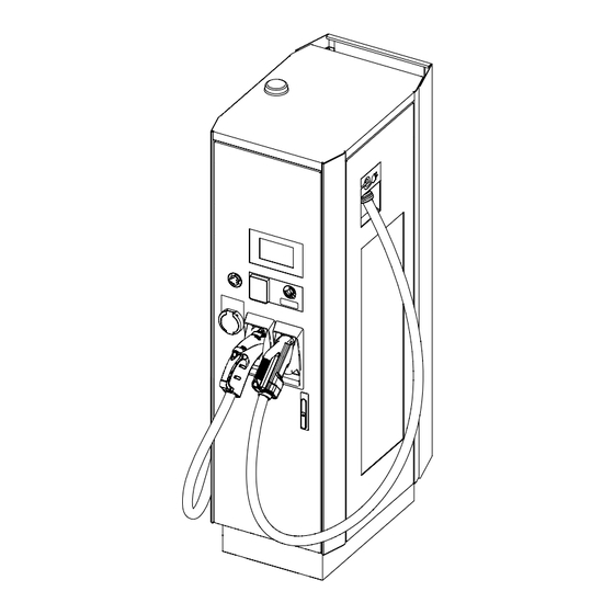
Page 20: Overview
“Operation and installation manual” - “Terra 94/124/184 - CE” Overview 3.3.1 Overview of the EVSE, outside C version CC version CCT version CJ version CJT version... - Page 21 Description Ref. Part Function Wireless antenna To send and receive data via cellular signal To access the power modules and Communication and Front door control section Display Human-machine interface (HMI) RFID To read the information from an RFID card Payment terminal To pay for the charging session Emergency stop button To stop the EVSE when there is an emergency...
-
Page 22: Overview Of The Evse, Inside
“Operation and installation manual” - “Terra 94/124/184 - CE” 3.3.2 Overview of the EVSE, inside Ref. Part Function Communication and control section To allocate the communication and control board To provide the physical containment for various power Power modules components Main AC switch Input protection of the EVSE Main AC terminals... -
Page 23: Overview - Foundation And Cables Entry
Description 3.3.3 Overview - Foundation and cables entry Ref. Part Function Concrete foundation To anchor the EVSE on the floor and route the cables (Global ID ABB4EPY420074R1) Cable inlet To route the cables inside the concrete foundation Dowel To anchor the EVSE to the concrete foundation 3.3.4 Overview - Air openings and filters Ref. -
Page 24: Overview Of The Cable Management System (Option)
“Operation and installation manual” - “Terra 94/124/184 - CE” 3.3.5 Overview of the cable management system (option) Ref. Part Function Top attachment point Upper fixing point to the EVSE Cable management system Bottom attachment point Lower installation point to the EVSE Cable clamp To hook the charging cable... -
Page 25: System Overview
Description System Overview Ref. Part Function Electrical Vehicle to be recharged Parking space To park the EV during charge session Front of the EVSE Side of EVSE with EV connectors and HMI (User Interface) EVSE EV charger AC input cable To supply the input AC voltage to the EVSE Power distribution board AC grid input protection and distribution circuits... -
Page 26: Concurrent Power Allocation
“Operation and installation manual” - “Terra 94/124/184 - CE” 3.5.2 Concurrent power allocation 0 - 99% 0 - 99% 100% The power can be allocated in this way: - EV1 and EV2 each receive a maximum of 50 % power from the EVSE until they are fully charged. -
Page 27: Block Diagram
Description Block diagram 3.6.1 Terra xx4 - C, CC and CJ models EVSE Main AC Switch MV/LV Distribution SWITCH MATRIX CCS2 PM 1 RCD + AC/DC Meter fuse PM 2 AC/DC PM 3 AC/DC AC Contactor CCS2 PM 4 AC/DC PM 5 AC SPD AC/DC... -
Page 28: Terra Xx4 - Cct And Cjt Models
“Operation and installation manual” - “Terra 94/124/184 - CE” 3.6.2 Terra xx4 - CCT and CJT models EVSE Main AC Switch Type 2 MV/LV AC out AC out AC out Distribution Meter Contactor SWITCH MATRIX CCS2 PM 1 RCD + AC/DC Meter fuse... -
Page 29: Description Of The Touchscreen
Description Description of the touchscreen 3.7.1 General description of the layout Welcome First select your output. CHAdeMO Ref. Description Field to select the connector type Instruction field Information button Selected language Description of the buttons: Button Name Description To select the CCS connector CHAdeMo To select the CHAdeMo connector To select the AC socket (Type 2) -
Page 30: Rfid - Authorization To Charge
RFID Authorization shall be enabled by Charge Point Operator (CPO) OCPP server backend Cloud service portal ABB E-mobility provides a set of cloud-based tools to commission, monitor and troubleshoot the EVSE. NOTE Reach out to the local entity of ABB E-mobility for more information:... -
Page 31: Options
Description 3.10 Options 3.10.1 Fiscal metering system The EVSE can optionally be equipped with an energy metering system (consisting of DC or AC measurement depending on the configured outlets on the EVSE). The dedicated Meter display (07) on the front panel shows: A. -
Page 32: Tilt Sensors
EVSE display. NOTE Check with ABB E-mobility sales team the complete list of available payment terminals. 3.10.3.1 Alternative cellular modem The EVSE can be optionally equipped, in addition to the pre-installed cellular modem, with an alternative one for customer purpose. -
Page 33: Charging Connector
Description 3.10.4 Charging connector The EVSE can be delivered with different charging connectors on the EV charge cables: CCS 2 CHAdeMO AC socket, Type 2 NOTE For the current and voltage rating specifications, refer to the “10.1. Technical data”. 3.10.5 Cable management system The CMS (51) (cable management system) helps to retract and hold the cables in position when the EVSE is not in use. -
Page 34: Transport, Handling And Unpacking
4. Transport, handling and unpacking In this section are explained all the transport specification, including handling and unpacking procedures of the EVSE. Chapter recipients: • Owner • Qualified installer • Handling and transportation company... -
Page 35: Transport The Evse To The Site
Transport, handling and unpacking Transport the EVSE to the site A transport company delivers the EVSE close to the site. The movement of the EVSE to its final location is their responsibility. NOTE If you need to store the EVSE before installation, obey the ambient conditions for storage (refer to section “10.1.2. - Page 36 If the package is damaged and/or scratched check the external cosmetic of product by removing the protections. If damage is observed, document it and contact ABB E-mobility. • The pallet shall be intact and not damaged for a safe transportation and handling of the product.
-
Page 37: Preliminary Checks On Lifting Equipment
Transport, handling and unpacking 4.1.2 Preliminary checks on lifting equipment • Handling personnel must wear all appropriate and applicable personal protective equipment (PPE) and follow all the applicable Health and Safety measures applicable to the working area. • Handling operators must comply to all local regulations. •... - Page 38 “Operation and installation manual” - “Terra 94/124/184 - CE” DANGER • The forks need to be fully able to move into the pallet to provide full support and operated by trained staff. • Knowing the total weight, ropes and chains needs to be suitable and in safe conditions and operated by trained staff.
- Page 39 Transport, handling and unpacking • Ensure that the area is not accessible to unauthorized personnel and the personnel involved in handling the EV Charger are fully aware of the safety measures to apply when handling the EV Charger and keep sufficient distance away from the moving EV Charger.
-
Page 40: Lifting Of The Evse
“Operation and installation manual” - “Terra 94/124/184 - CE” Lifting of the EVSE WARNING • Risk of pinching or crushing, the EVSE is heavy • Make sure that the hoisting equipment can lift the EVSE safely • Obey the safety instructions that apply to the hoisting equipment •... -
Page 41: Access To The Inside Of Evse
Access to the inside of EVSE 5. Access to the inside of EVSE In this section are illustrated all the access procedures. Chapter recipients: • Qualified installer... -
Page 42: Front Door
“Operation and installation manual” - “Terra 94/124/184 - CE” Front door HAZARDOUS VOLTAGE Make sure that only qualified persons have access to the door key. NOTE There is one unique door key for each EVSE. 5.1.1 Open the front door Use the door key to unlock the upper and lower swing handle lock (03) and (17) to open the front door. -
Page 43: Close The Front Door
Access to the inside of EVSE 5.1.2 Close the front door In order to close the front door (02) of the EVSE, repeat the operations described in the “Open the front door“ section in reverse order. Sides doors When the front door (02) is open it is possible to access the side door opening systems: Left door (20) - Internal left door handle (A). -
Page 44: Border Covers
“Operation and installation manual” - “Terra 94/124/184 - CE” Border covers 5.3.1 Remove the border covers To access the fasten point between the EVSE and the floor is necessary to remove the Base cover (11). • Unscrew and remove the 8 fasteners of the base cover (11) on the rear side of the EVSE. -
Page 45: Main Ac Protection Barriers
Access to the inside of EVSE Main AC protection barriers In order to remove the Main AC protection barriers (44) is necessary to open the front (02) and right doors (13). The Main AC protection barriers (44) are located over the Main AC terminals (33) or AC input fuse (32). 5.4.1 Remove the Main AC protection barriers To access the Main AC terminals (33) is necessary to remove the Main AC protection barriers (44). -
Page 46: Install The Main Ac Protection Barriers
“Operation and installation manual” - “Terra 94/124/184 - CE” 5.4.2 Install the Main AC protection barriers At the end of operation on the Main AC terminals (33) or AC input fuse (32), is necessary to install the Main AC protection barriers (44) to ensure the safety of the EVSE. -
Page 47: Installation
Installation 6. Installation In this section are illustrated all the installation procedure. Chapter recipients: • Owner • Qualified installer • Handling company... -
Page 48: Unpacking
“Operation and installation manual” - “Terra 94/124/184 - CE” Unpacking WARNING Packaging elements (cardboard, cellophane, staples, adhesive tape, straps, etc.) may cause cuts and/or injuries if not handled with care. They should be removed with the proper equipment. NOTE The components of the packaging must be disposed in accordance with the regulations in force in the country of installation. - Page 49 Installation • Spread the cardboard on both sides. • Remove the two main parts of the packaging. • Take out the supplied components. Refer to “6.1.2. Components supplied with the EVSE”). • Remove the internal foams. • Remove the charging cable from the box.
-
Page 50: Components Supplied With The Evse
“Operation and installation manual” - “Terra 94/124/184 - CE” 6.1.2 Components supplied with the EVSE When the EVSE is unpacked, make sure all components supplied with the EVSE are present: Component Description Quantity Keys to open the EVSE front door Nuts to install the EVSE to the floor 4 + 8 + 4 Bolts + Washers + Nuts to install AC and... - Page 51 Installation The EVSE can be equipped with two types of cable clamp used to hook the charging cable on the CMS. Follow the steps below regarding the clamp that is present on the EVSE: TYPE 1 TYPE 2 • Install the cable clamp (53), one on each charging cable, •...
-
Page 52: Floor Space Requirements
“Operation and installation manual” - “Terra 94/124/184 - CE” 6.2.2 Floor space requirements Parameter Description Specification [mm] EVSE (front side indicated by red arrow) Example of approved bollard location Space to open the side doors Reduced side space to install the bollards Space needed to secure the removable base cover Increased front space to install the bollards Space to open the front door... -
Page 53: Prepare The Foundation
6.2.3 Prepare the foundation The EVSE can be installed on: • Prefabricated foundation (to be ordered from ABB E-mobility). In this case follow the instruction below to install the EVSE • Custom foundation. In this case use the drawing of the “11.5. - Page 54 “Operation and installation manual” - “Terra 94/124/184 - CE” • Pour concrete (C) around the Concrete foundation (45) to lock in place the conduits and the foundation itself. 6.2.3.2 Prepare the custom foundation The EVSE must be installed on a custom foundation suitable to support the weight of the equipment. Use the drawing of the “11.5.
-
Page 55: Install The Evse On The Foundation
Installation 6.2.4 Install the EVSE on the foundation • Open the front and right doors. Refer to section “5.1. Front door” “5.2. Sides doors” • Remove the Main AC protection barrier (44). Refer to “5.4.1. Remove the Main AC protection barriers”. - Page 56 “Operation and installation manual” - “Terra 94/124/184 - CE” • Open the front (02) and right doors (13) of the EVSE when is near to ground. Refer to section “5.1. Front door” “5.2. Sides doors” • Carefully lower the EVSE on the floor/foundation. During this phase the cables must be aligned and routed through the Cables entry plate (43): −...
-
Page 57: Electrical Connection
Electrical connection 7. Electrical connection In this section are listed all the electrical connection procedure. Chapter recipients: • Qualified installer... -
Page 58: Electrical Connection - Preliminary Operations
“Operation and installation manual” - “Terra 94/124/184 - CE” Electrical connection - preliminary operations 7.1.1 Supported low voltage network types The following network configurations are permitted for the connection of the EVSE: • TN-C • TN-C-S • TN-S • TT NOTE Operation in IT networks is not allowed. -
Page 59: External Ac Input Protections
Electrical connection 7.1.2 External AC input protections General schematic to identify the position of AC protection devices. Parameter Description Medium voltage network Medium voltage breaker Medium voltage/Low voltage transformer Low voltage protection devices: - Overcurrent protection - Residual Current Protection (RCD) - Surge Protection Device (SPD) Type 1 This information does not supersede any legal regulations. -
Page 60: Internet Access
NOTE Signal strength must be greater than -85 dBm (RSSI) and measured with a cellular signal meter. NOTE The EVSE supports SIM cards provided by ABB only. Any other types of SIM cards are not supported. 7.1.3.2 Internet via Ethernet connection If the cellular connection is not available, Ethernet connection must be made to the charger. -
Page 61: Protective Earth (Pe) Connection
Electrical connection Protective earth (PE) connection HAZARDOUS VOLTAGE The EVSE’s protective earth (PE) connection is mandatory. The EVSE must be earthed via the connection points marked with the protective earth symbol and using a cable with an appropriate conductor cross-section for the maximum ground fault current that the system might experience. -
Page 62: Ac Input Connection
“Operation and installation manual” - “Terra 94/124/184 - CE” AC input connection HAZARDOUS VOLTAGE Before carrying out any operation, check that any external switch of voltage sources (upstream to the EVSE) are in OFF position and check for voltage absence on the AC conductors! The EVSE must be connected to the AC input using cables with an appropriate conductor cross-section for minimize loss of power. -
Page 63: Secure The Input Connection Cables
Electrical connection • Install the Main AC protection barriers (44) by sliding them on the Main AC switch (32). Refer to “5.4.2. Install the Main AC protection barriers” for the installation procedure. NOTE Each Main AC protection barrier (44) has 4 knockouts, on the bottom side, to be removed based on the diameter of the cable: A - 12 mm... -
Page 64: Ethernet Connection
The charger’s Ethernet communication, if the Ethernet port is enabled and an on-site Internet connection is available, allows to the charger to transmit telemetry data to the ABB EVCI Cloud without the need to install any additional devices (the logging functionality is already integrated into the charger by default). ABB’s EVCI cloud platform consists of several solutions for monitoring and management of chargers in real-time. -
Page 65: Tilt Sensor (Optional)
NOTE The circuit breaker, 24 V DC power supply delivered from an UPS and all other external components to the EVSE are not within the scope of ABB E-mobility, therefore are not provided. NOTE Refer to “10.1.1. -
Page 66: Connect The Tilt Sensor (Option)
“Operation and installation manual” - “Terra 94/124/184 - CE” 7.6.1 Connect the tilt sensor (option) The connection of the tilt sensor (37) must be made on screw terminal block (39). • Cut the 4 wires to connect the tilt sensor, so that they reach the lower side of terminal block (39). -
Page 67: Operation And Correct Use
Operation and correct use 8. Operation and correct use This chapter will give instruction on the correct use of the EVSE. Chapter recipients: • Owner • Qualified installer • User... -
Page 68: Prepare For Commissioning Of The Evse
1. The qualified installer have to inform the owner that the EVSE is ready for commissioning 2. The owner/qualified installer must inform ABB E-mobility that the EVSE is installed correctly in order to schedule the commissioning and ensure that the site complies with these requirements: •... -
Page 69: Remove Condensation From The Cabinet
Operation and correct use 8.2.1 Remove condensation from the cabinet To remove condensation inside the charger, carry out the following procedure: • Perform the Total de-energization procedure. Refer to section “9.3. Total de-energization of the EVSE” • Open the front and right doors. Refer to section “5. -
Page 70: Charging Session
“Operation and installation manual” - “Terra 94/124/184 - CE” Charging session 8.3.1 Start a charging session • Park the electric vehicle with the charge inlet within reach of the connector. • Turn off the electric vehicle. • On the touchscreen, select the applicable charging connector button. NOTE If you skip this step, the EVSE selects the correct connector automatically when you connect the EV charge cable to the EV. -
Page 71: Emergency Stop Of A Charge Session
Operation and correct use 8.3.3 Emergency stop of a charge session NOTE Stop by emergency button is possible only if the optional button is installed on the front door of the EVSE. The EVSE stops the charge session when the emergency stop is pushed. Only push the emergency stop if there is an emergency! If there is an emergency: •... -
Page 72: Maintenance And Troubleshooting
“Operation and installation manual” - “Terra 94/124/184 - CE” 9. Maintenance and troubleshooting In this section the user will be instructed on maintenance and cleaning procedures. Preliminary requirements • Owner • Qualified installer • ABB E-mobility Service or authorized service partners... -
Page 73: Routine Maintenance
In addition to routine maintenance, a scheduled component replacement shall be performed to guarantee the continuity of operation of the EVSE. Contact ABB E-mobility for more information on available Service Level Agreements. HAZARDOUS VOLTAGE Operation on the inside of the EVSE shall be performed only by authorized or trained personnel. -
Page 74: Troubleshooting
If you get a problem on the EVSE, the below troubleshooting can help to resolve the problem. NOTE If you cannot find a solution for the problem, please reach out to the local entity of ABB E-mobility B.V. for support: https://e-mobility.abb.com/contact-centers/. -
Page 75: Total De-Energization Of The Evse
Maintenance and troubleshooting Total de-energization of the EVSE The total de-energization instruction specifies the use of mandatory PPE, tools, equipment and operations to carry out the electrical de-energization of the EVSE. NOTE This instruction does not supersede any legal regulations. The local regulations may impose requirements not reflected in this standard. -
Page 76: Safety Equipment And Tools
“Operation and installation manual” - “Terra 94/124/184 - CE” 9.3.6 Safety equipment and tools The below table shows the required tools and equipment’s that are necessary to perform the steps of the total de-energization procedure. NOTE For safety reasons, service engineers shall check the functionality of the tools before start of work. Tools and Equipment Description Voltage detector (EN 61243-2) - Page 77 Maintenance and troubleshooting 7. Insulating barrier removal: Remove the Main AC protection barrier (44) on the bottom side of AC main switch. 8. Earthing and short circuiting incoming line assessment: Is needed to make the earth and short-circuit connection on the main AC incoming line in presence of a site configured as below: MV distribution panel LV distribution panel...
- Page 78 “Operation and installation manual” - “Terra 94/124/184 - CE” 10. Technical data This chapter contains information about the models, details of the EVSE, characteristics and technical data, overall dimensions and EVSE identification. A description of the EVSE characteristics is provided to identify its main components and specify the technical terminology used in the manual.
-
Page 79: Technical Data
Technical data 10.1 Technical data 10.1.1 Technical data table Terra 94 CE Terra 124 CE Terra 184 CE EVSE configuration Charging standard Mode 4 1 or 2 DC output (based on the configuration) Number of outputs 1 AC output socket (based on the configuration) 1 on the configuration C Number of EV served 2 on the configuration CC or CJ... - Page 80 “Operation and installation manual” - “Terra 94/124/184 - CE” Terra 94 CE Terra 124 CE Terra 184 CE Mechanical Without CMS: 565 x 1930 x 880 mm Dimensions (W x H x D) With two CMS: 847 x 1930 x 922 mm Mounting Type Floor mounted Weight...
-
Page 81: Environmental Conditions
1 year Starting from manufacturing date 2. Contact ABB if the EVSE has been stored for longer periods 3. Protected from the influences of meteorological conditions 4. Transportation conditions are those that the product can be exposed to while transported and handled in its original package 5. -
Page 82: Torque Specification
“Operation and installation manual” - “Terra 94/124/184 - CE” Ethernet CAT 5e (recommend) CAT 6 (high presence of electromagnetic interference and/or noise) Ethernet cable diameter (cable entry plate) 10...17 mm Material serviceable for outdoor, Insulation UV-protected and suitable for use in underground ducts according to local rules. -
Page 83: Terra 94 - Output Power And Current Vs Output Voltage Curve
Technical data 10.4 Terra 94 - Output power and current Vs output voltage curve EVSE output power may be reduced by: • Environmental conditions(e.g ambient temperature) • Time between charging sessions • E-Vehicle power peak duration and battery State of Charge (SoC) 10.4.1 CCS2 (400 A) - 1 session 100000 90000... -
Page 84: Terra 124 - Output Power And Current Vs Output Voltage Curve
“Operation and installation manual” - “Terra 94/124/184 - CE” 10.5 Terra 124 - Output power and current Vs output voltage curve EVSE output power may be reduced by: • Environmental conditions(e.g ambient temperature) • Time between charging sessions • E-Vehicle power peak duration and battery State of Charge (SoC) 10.5.1 CCS2 (400 A) - 1 session 140000 130000... -
Page 85: Terra 184 - Output Power And Current Vs Output Voltage Curve
Technical data 10.6 Terra 184 - Output power and current Vs output voltage curve EVSE output power may be reduced by: • Environmental conditions(e.g ambient temperature) • Time between charging sessions • E-Vehicle power peak duration and battery State of Charge (SoC) 10.6.1 CCS2 (400 A) - 1 session 180000 160000... -
Page 86: Attachments
“Operation and installation manual” - “Terra 94/124/184 - CE” 11. Attachments In this section additional technical drawing, specification, schematics are given. NOTE If you need further information, reach out to the local entity of ABB E-mobility B.V. for support: https://e-mobility.abb.com/contact-centers/ Chapter recipients: • Owner... -
Page 87: Evse Dimensions
Attachments 11.1 EVSE dimensions 11.1.1 EVSE dimensions without CMS NOTE The measurements in the drawing are in inches and millimeters [in (mm)] 127.5 38.5... -
Page 88: Evse Dimensions With Two Cms
“Operation and installation manual” - “Terra 94/124/184 - CE” 11.1.2 EVSE dimensions with two CMS NOTE The measurements in the drawing are in inches and millimeters [in (mm)] 127.5... -
Page 89: Height Of User Operable Elements
Attachments 11.2 Height of user operable elements NOTE The measurements in the drawing are in millimeters (mm) Parameter Description Ground / Foundation level Highest height of user operable element on the EVSE (payment terminal) Lowest height of user operable element on the EVSE (optional meter display) Height of the EVSE base... -
Page 90: Center Of Gravity (Without Cms)
“Operation and installation manual” - “Terra 94/124/184 - CE” 11.3 Center of gravity (without CMS) The measurement in the drawing are releted to T184 model (with two charging cables). NOTE For the T94 and T124 models, take into account a tolerance of ±3 in (77 mm) for each measurement. -
Page 91: Prefabricated Foundation
Attachments 11.4 Prefabricated foundation The drawing of the prefabricated foundation (Global ID ABB4EPY420074R1) shows all the necessary measurements. NOTE The measurements in the drawing are in millimeters (mm). On the top side of the prefabricated foundation an arrow indicates the front side. The weight of the concrete foundation is about 450 kg. -
Page 92: Custom Foundation - Evse Footprint
“Operation and installation manual” - “Terra 94/124/184 - CE” 11.5 Custom foundation - EVSE footprint The drawing (top view) shows all the necessary measurements to prepare a custom foundation: • drill the holes to fasten the EVSE to the floor/basement (in yellow) •... -
Page 93: Charging Cable Reach
Attachments 11.6 Charging cable reach 3.5 m 3.5 m 2.5 m 2.5 m 3.0 m 3.0 m 11.6.1 Charging cable reach without CMS 3.5 m 3.4 m 3.4 m 3.5 m 3.5 m 3.5 m Cable lenght Left side charging cable Right side charging cable 2.5 m 2.5 m... - Page 94 — https://e-mobility.abb.com/...
Need help?
Do you have a question about the Terra 94-CE and is the answer not in the manual?
Questions and answers