Table of Contents
Advertisement
Quick Links
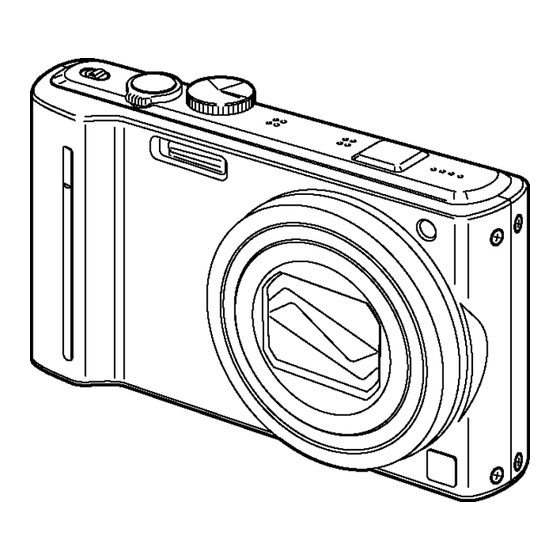
DMC-TZ10EB
Model No.
DMC-TZ10EE
DMC-TZ10EF
DMC-TZ10EG
DMC-TZ10EP
DMC-TZ10GC
DMC-TZ10GN
DMC-TZ10SG
DMC-ZS7P
DMC-ZS7PC
DMC-ZS7PU
DMC-ZS7GD
DMC-ZS7GH
DMC-ZS7GK
DMC-ZS7GT
VOL.1
Colours
(S)....................Silver Type (except DMC-TZ10EF,
ZS7GD)
(K)....................Black Type
(A)....................Blue Type (only DMC-TZ10EB/EE/EG/
EP/GN, ZS7P/PC/PU)
(R)....................Red Type (except DMC-ZS7GT/GD/PC)
(T)....................Brown Type (only DMC-TZ10EE/EF/EG/
EP/GC, ZS7GH/GT/GK)
(N)....................Gold Type (only DMC-TZ10GC/SG,
ZS7GH/GK)
© Panasonic Corporation 2010.
Unauthorized copying and distribution is a violation
of law.
ORDER NO.DSC1002018CE
B26
Digital Camera
Advertisement
Chapters
Table of Contents


Need help?
Do you have a question about the LUMIX DMC-TZ10EB and is the answer not in the manual?
Questions and answers