Table of Contents
Advertisement
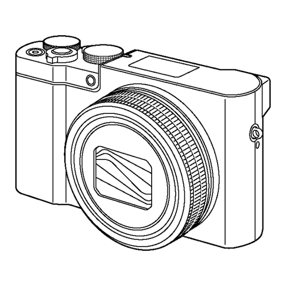
DMC-TZ100EB
Model No.
DMC-TZ100EF
DMC-TZ100EG
DMC-TZ100EP
DMC-TZ101EF
DMC-TZ101EG
DMC-TZ110GA
DMC-TZ110GN
DMC-ZS100P
DMC-ZS100PP
DMC-ZS110GD
DMC-ZS110GH
DMC-ZS110GK
Colours
Product Color
(S)....................Silver Type
(K)....................Black Type
(R)....................Red Type (Only TZ100EB/TZ101EF)
© Panasonic Corporation 2016.
Unauthorized copying and distribution is a violation
of law.
ORDER NO.DSC1603003CE
B26
Digital Camera
Advertisement
Table of Contents


Need help?
Do you have a question about the LUMIX DMC-TZ100EB and is the answer not in the manual?
Questions and answers