
Related Manuals for Peak PCAN-Ethernet Gateway FD DR


Summary of Contents for Peak PCAN-Ethernet Gateway FD DR
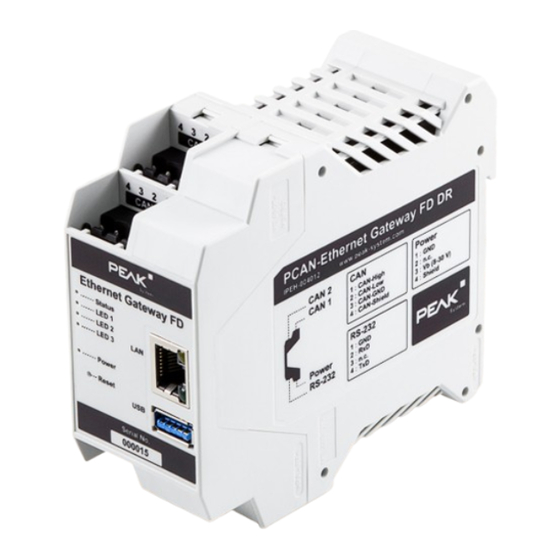
- Page 1 PCAN-Ethernet Gateway FD DR User Manual User Manual 2.0.0 © 2024 PEAK-System Technik GmbH...
-
Page 2: Imprint
IPEH-004012 Imprint PCAN is a registered trademark of PEAK-System Technik GmbH.CANopen®, CANopen FD®and CiA® are registered community trade marks of CAN in Automation e.V. All other product names in this document may be the trademarks or registered trademarks of their respective companies. -
Page 3: Table Of Contents
3.3 Installation 4 Operation 4.1 Status LEDs 4.2 Reboot and Restore 4.3 Signal Delay 5 Configuration 5.1 Structure of the Website 5.2 Status 5.3 Routing 5.4 Filters Contents PCAN-Ethernet Gateway FD DR User Manual 2.0.0 © 2024 PEAK-System Technik GmbH... - Page 4 6.2 Bidirectional Data Transmission 6.3 Filtering Single CAN IDs 7 Technical Specifications Appendix A CE Certificate Appendix B UKCA Certificate Appendix C Dimension Drawing Appendix D Disposal Contents PCAN-Ethernet Gateway FD DR User Manual 2.0.0 © 2024 PEAK-System Technik GmbH...
-
Page 5: Introduction
1 Introduction The PCAN-Ethernet Gateway FD DR allows access to classic CAN or modern CAN FD buses via an IP network. On top of that, CAN buses can be connected to each other via IP using multiple devices. CAN frames are wrapped in TCP or UDP message packets and then forwarded via the IP network from one device to another. -
Page 6: Properties At A Glance
Voltage supply from 8 to 30 V Operating temperature range from -40 to +70 °C (-40 to +158 °F) Fan for active cooling when a temperature limit is exceeded 1 Introduction PCAN-Ethernet Gateway FD DR User Manual 2.0.0 © 2024 PEAK-System Technik GmbH... -
Page 7: Scope Of Supply
1.2 Scope of Supply PCAN-Ethernet Gateway FD DR in DIN rail plastic casing Mating connectors for both CAN channels, RS-232, and power supply (Phoenix Contact MSTB 2,5/4-ST BK - 1756298) RJ-45 network patch cord (2 m) Manual in PDF format... -
Page 8: Connectors And Control Elements
CAN connector 1 and 2 The mating connectors (Phoenix Contact MSTB 2,5 / 4-ST BK - 1756298) are included in the scope of supply. 2 Connectors and Control Elements PCAN-Ethernet Gateway FD DR User Manual 2.0.0 © 2024 PEAK-System Technik GmbH... - Page 9 Do the following to activate the internal termination: Risk of short circuit! Soldering on the PCAN-Ethernet Gateway FD DR may only be performed by qualified electrical engineering personnel. Attention! Electrostatic discharge (ESD) can damage or destroy components on the card.
- Page 10 This unlocks the snap locks. 3. Pull the two casing sections apart. Open casing with the back side of the board to activate the internal termination 2 Connectors and Control Elements PCAN-Ethernet Gateway FD DR User Manual 2.0.0 © 2024 PEAK-System Technik GmbH...
- Page 11 5. Re-insert the circuit board into the guide slot of the counterpart of the casing and push both parts together until the snap locks engage with a clicking sound. 2 Connectors and Control Elements PCAN-Ethernet Gateway FD DR User Manual 2.0.0 © 2024 PEAK-System Technik GmbH...
-
Page 12: Rs-232
Pin assignment Power connector The mating connector (Phoenix Contact MSTB 2,5 / 4-ST BK - 1756298) is included in the scope of supply. 2 Connectors and Control Elements PCAN-Ethernet Gateway FD DR User Manual 2.0.0 © 2024 PEAK-System Technik GmbH... -
Page 13: Lan
Ethernet Gateway FD DR. USB port 2.6 Reset Button The PCAN-Ethernet Gateway FD DR can be restarted or reset with the Reset button. You can find more information in section 4.2 Reboot and Restore. 2 Connectors and Control Elements PCAN-Ethernet Gateway FD DR User Manual 2.0.0... -
Page 14: Leds
2.7 LEDs The PCAN-Ethernet Gateway FD DR has LEDs for device status and power supply, two LAN LEDs, and LED 1 to 3. For more information, see section 4.1 Status LEDs. 2 Connectors and Control Elements PCAN-Ethernet Gateway FD DR User Manual 2.0.0... -
Page 15: Commissioning
3 Commissioning The PCAN-Ethernet Gateway FD DR is configured via a web interface. Therefore, the gateway must be connected via LAN to a computer, located in the same logical network as your gateway (192.168.1.xxx). 3.1 Establish First Connection During initial operation or after resetting to factory defaults, you must preconfigure the PCAN-Gateway for your LAN. - Page 16 (see the label on the left side of the device). IP and access information on the left side of the device Address bar of the web browser This opens the configuration website. 3 Commissioning PCAN-Ethernet Gateway FD DR User Manual 2.0.0 © 2024 PEAK-System Technik GmbH...
-
Page 17: Basic Configuration
Internet or make it easily accessible. Do not give the new login data carelessly to third parties nor send it by e-mail. 3 Commissioning PCAN-Ethernet Gateway FD DR User Manual 2.0.0 © 2024 PEAK-System Technik GmbH... - Page 18 3. Confirm the entered data with |Save Settings|. You are automatically forwarded to the new IP address. The basic setup of the device is now completed. 3 Commissioning PCAN-Ethernet Gateway FD DR User Manual 2.0.0 © 2024 PEAK-System Technik GmbH...
- Page 19 You are automatically logged out and the basic setup of the device is now completed. When the PCAN-Gateway is installed in the LAN, it automatically receives its new address data via DHCP. 3 Commissioning PCAN-Ethernet Gateway FD DR User Manual 2.0.0 © 2024 PEAK-System Technik GmbH...
-
Page 20: Installation
1. Connect each of the two CAN ports with the affiliated CAN network. 2. Connect the RJ-45 connector using a LAN cable to the IP network. 3. Connect the PCAN-Ethernet Gateway FD DR to a suitable power supply (8 - 30 V). 3 Commissioning PCAN-Ethernet Gateway FD DR User Manual 2.0.0... - Page 21 The PCAN-Ethernet Gateway FD DR starts automatically. When the status LED is blinking green the device is ready and the current configuration is executed. Note: A High-speed CAN bus needs to be electrically terminated on both ends using resistors of 120 Ω. The device does not have an internal termination.
-
Page 22: Operation
4 Operation Front side with LEDs and Reset button 4.1 Status LEDs The PCAN-Ethernet Gateway FD DR has LEDs for device status and power supply as well as two LAN LEDs, which indicate the following conditions: 4 Operation PCAN-Ethernet Gateway FD DR User Manual 2.0.0... -
Page 23: Reboot And Restore
In addition, there are the LEDs 1 to 3, which are also used when restoring the device. 4.2 Reboot and Restore The PCAN-Ethernet Gateway FD DR can be rebooted or restored using the reset button. The reset button is located behind a small hole on the front of the device and can be pressed with a paper clip, for example. - Page 24 Phase B: Restoring the Active Partition The PCAN-Ethernet Gateway FD DR uses two partitions for storing the software. One of these partitions is active and is started when the device is put into operation. In case of an update, the new software is installed on the inactive partition. The inactive partition is activated and the device is rebooted.
- Page 25 The Restore website appears. Note: If the boot process on both partitions cannot be executed completely 10 times in a row or is interrupted by voltage loss, the PCAN-Ethernet Gateway FD DR automatically activates the restore partition. Functionality of the Restore Website:...
-
Page 26: Signal Delay
The transmit time of the signal in the IP network depends on the expansion and structure of the network as well as the configuration of the message forwarding. Therefore, a fixed value cannot be specified. 4 Operation PCAN-Ethernet Gateway FD DR User Manual 2.0.0 © 2024 PEAK-System Technik GmbH... -
Page 27: Configuration
5 Configuration The configuration of the PCAN-Ethernet Gateway FD DR is done via a comfortable web interface. Enter the IP address of your PCAN-Gateway into the address bar of your browser. Afterwards, the configuration website opens. Besides providing a variety of status information, the website can be used to manage settings for the PCAN-Gateway, communication interfaces, message routing, and filters. -
Page 28: Structure Of The Website
The subpages of Routing can be used to add, manage, edit, or delete routes, as well as to search for other devices in the network The subpages of Filters can be used to add, edit, or delete filters 5 Configuration PCAN-Ethernet Gateway FD DR User Manual 2.0.0 © 2024 PEAK-System Technik GmbH... - Page 29 In some cases, additional information is displayed as a tooltip when you hover the mouse cursor over the icon. 5 Configuration PCAN-Ethernet Gateway FD DR User Manual 2.0.0 © 2024 PEAK-System Technik GmbH...
- Page 30 OFF / inactive Warning! The execution / function is prevented. The problem is well known and can be eliminated. Attention! An error prevents the execution / function. 5 Configuration PCAN-Ethernet Gateway FD DR User Manual 2.0.0 © 2024 PEAK-System Technik GmbH...
-
Page 31: Status
On the Routing > Manage Routes page, existing routes can be managed, edited, and deleted On the Routing > Add Route page, new routes can be created 5 Configuration PCAN-Ethernet Gateway FD DR User Manual 2.0.0 © 2024 PEAK-System Technik GmbH... - Page 32 On the Filter > Manage Filters page, existing filters can be managed, edited, and deleted On the Filter > Add Filter page new filters can be created 5 Configuration PCAN-Ethernet Gateway FD DR User Manual 2.0.0 © 2024 PEAK-System Technik GmbH...
-
Page 33: Routing
On the Routing > Add Route page, new routes can be created Detected Devices: This table shows all PEAK-System gateways that were detected during the last network broadcast scan. If no other devices are currently in the network or no scan has been performed, this table will not be shown. - Page 34 With a Receive route the PCAN-Gateway receives data via the IP interface and forwards it to a CAN channel. The IP address is displayed in this case as Local IP 5 Configuration PCAN-Ethernet Gateway FD DR User Manual 2.0.0 © 2024 PEAK-System Technik GmbH...
- Page 35 Detailed information can be found in section 5.3.2 Add / Edit Route. |Add Route|: This button opens the Routing > Add Route page on which you can set up a new message forwarding instance. 5 Configuration PCAN-Ethernet Gateway FD DR User Manual 2.0.0 © 2024 PEAK-System Technik GmbH...
- Page 36 In Expert mode (see section 5.6.2 User Management) detailed connection status information are displayed. With the |Reset| button you can reset the values of the route to 0. 5 Configuration PCAN-Ethernet Gateway FD DR User Manual 2.0.0 © 2024 PEAK-System Technik GmbH...
- Page 37 PCAN-Gateway handshake off: (Expert mode only) If this checkbox is active, no handshake will be performed and therefore no status information will be gathered for this route. Use this option for communication with your own application. 5 Configuration PCAN-Ethernet Gateway FD DR User Manual 2.0.0 © 2024 PEAK-System Technik GmbH...
- Page 38 Port 45321 is reserved for the transmission of status information and to perform a handshake between PCAN- Gateways. 5 Configuration PCAN-Ethernet Gateway FD DR User Manual 2.0.0 © 2024 PEAK-System Technik GmbH...
- Page 39 Filters are joined with: This property specifies how multiple filters are linked. If you use several Whitelist filters, you should choose Logical OR. If you attach multiple Blacklist filters to a single route, the selection Logical AND is recommended. 5 Configuration PCAN-Ethernet Gateway FD DR User Manual 2.0.0 © 2024 PEAK-System Technik GmbH...
- Page 40 If a device is removed from the network, it will remain visible in the list of detected devices until the scan is performed again and the list is updated. 5 Configuration PCAN-Ethernet Gateway FD DR User Manual 2.0.0 © 2024 PEAK-System Technik GmbH...
- Page 41 Detected Devices: This table shows all PEAK-System gateways that were detected during the last network broadcast scan. If no other devices are currently in the network or no scan has been performed, this table will not be shown. Each PCAN-Gateway is displayed with its product name, the custom device name, MAC address, and serial number.
-
Page 42: Filters
Notes: Hover this icon with the mouse cursor to display the user notes of this filter. The icon is not visible if no user notes are available. 5 Configuration PCAN-Ethernet Gateway FD DR User Manual 2.0.0 © 2024 PEAK-System Technik GmbH... - Page 43 For this, the current settings are loaded into the form fields. Editing a filter is done via the page Filters > Manage Filters. 5 Configuration PCAN-Ethernet Gateway FD DR User Manual 2.0.0 © 2024 PEAK-System Technik GmbH...
- Page 44 This can be done via the slider (JavaScript support required) or with the input forms. From: This value marks the lower limit of the filter range To: This value marks the upper limit of the filter range 5 Configuration PCAN-Ethernet Gateway FD DR User Manual 2.0.0 © 2024 PEAK-System Technik GmbH...
- Page 45 Example for 11 Bit identifiers: Meaning Acceptance Code Acceptance Mask CAN messages with an ID matching this binary value, are accepted. X means that this bit position does not matter. 5 Configuration PCAN-Ethernet Gateway FD DR User Manual 2.0.0 © 2024 PEAK-System Technik GmbH...
- Page 46 Finally you can create the new filter with the |Add Filter| button or save the changes after editing with the |Save Settings| button. 5 Configuration PCAN-Ethernet Gateway FD DR User Manual 2.0.0 © 2024 PEAK-System Technik GmbH...
-
Page 47: Network
Channel: The channel number of the CAN interface. This number is used to select the intended interface while creating a route. Status: The LED indicates the state of the CAN channel. 5 Configuration PCAN-Ethernet Gateway FD DR User Manual 2.0.0 © 2024 PEAK-System Technik GmbH... - Page 48 With the Reset button you can reset the CAN channel. In Expert mode (see section 5.6.2 User Management) further detailed information is displayed. 5 Configuration PCAN-Ethernet Gateway FD DR User Manual 2.0.0 © 2024 PEAK-System Technik GmbH...
- Page 49 Set with register values. Nominal Bit Rate: For setting the nominal bit rate, click the drop-down menu and select the value that is used on the connected CAN bus. 5 Configuration PCAN-Ethernet Gateway FD DR User Manual 2.0.0 © 2024 PEAK-System Technik GmbH...
- Page 50 User Notes: Additional information with a length of 125 characters can be entered for each CAN channel. This text is available while route creation or editing. 5 Configuration PCAN-Ethernet Gateway FD DR User Manual 2.0.0 © 2024 PEAK-System Technik GmbH...
- Page 51 The Synchronization segment is always 1 and is used for the synchronization of each bus node. The sampling time (sample point) is determined via Time Segments 1 and 5 Configuration PCAN-Ethernet Gateway FD DR User Manual 2.0.0 © 2024 PEAK-System Technik GmbH...
- Page 52 20 kbit/s to 10 Mbit/s. The data bit rate must be equal or higher than the nominal bit rate. By clicking on the Save Settings| button you can save your previously defined bit rates. 5 Configuration PCAN-Ethernet Gateway FD DR User Manual 2.0.0 © 2024 PEAK-System Technik GmbH...
- Page 53 Time segment values instead of the Phase and Propagation segment values. The bit rate register string can be generated with the free applications Bit Rate Calculation Tool or PCAN-View from PEAK-System. Examples: 500 kbit/s Nominal BR, 80% Sample Point =...
- Page 54 IP address of the PCAN-Gateway to access the configuration website. Furthermore, the IP address may change after a restart of the device or the DHCP server. In this case the existing routes won't work. 5 Configuration PCAN-Ethernet Gateway FD DR User Manual 2.0.0 © 2024 PEAK-System Technik GmbH...
- Page 55 Gateway: Enter the IP address (IPv4) of the gateway that manages the IP network. Proceed with the same guidelines as outlined for local IP address entry. Entering a gateway address is optional. 5 Configuration PCAN-Ethernet Gateway FD DR User Manual 2.0.0 © 2024 PEAK-System Technik GmbH...
- Page 56 Connecting to the device is only possible by respectively adapting your computer’s IP address to the different network that the device is in. 5 Configuration PCAN-Ethernet Gateway FD DR User Manual 2.0.0 © 2024 PEAK-System Technik GmbH...
-
Page 57: Device
On the Device > Configuration page it is possible to assign a custom name and description to the device. In addition to that, different import and export options are available. 5 Configuration PCAN-Ethernet Gateway FD DR User Manual 2.0.0 © 2024 PEAK-System Technik GmbH... - Page 58 Use the button on the left side to select a configuration file (*. ini). To start the restoration process, click the | Import| button located on the right. 5 Configuration PCAN-Ethernet Gateway FD DR User Manual 2.0.0 © 2024 PEAK-System Technik GmbH...
- Page 59 (see the label on the left side of the device). The PCAN-Gateway is then reachable under the default IP address. 5 Configuration PCAN-Ethernet Gateway FD DR User Manual 2.0.0 © 2024 PEAK-System Technik GmbH...
- Page 60 Once you have activated the interface and Enable Configuration, the PCAN-Gateway can be configured without logging in. Detailed information about the JSON interface is included in the PCAN- Gateway developer documentation. 5 Configuration PCAN-Ethernet Gateway FD DR User Manual 2.0.0 © 2024 PEAK-System Technik GmbH...
- Page 61 Reset after Login: If you deactivate this checkbox, the display mode is not reset after a new login. 5 Configuration PCAN-Ethernet Gateway FD DR User Manual 2.0.0 © 2024 PEAK-System Technik GmbH...
- Page 62 In addition, the CPU load is presented in a graph over time. Temperatures The PCAN-Ethernet Gateway FD DR provides several sensors for monitoring the operating temperatures, in particular the temperatures of the CPU, the CPU board, and the power board.
- Page 63 This number can be found on the pages Device > Software Update and Device in the footer of the website. Current product updates can be downloaded on the PEAK-System website (www.peak-system.com). Please make sure to download the correct package for your device.
- Page 64 The currently active partition is marked red. Each form provides buttons to download the config file or to activate and reboot the currently not active partition. 5 Configuration PCAN-Ethernet Gateway FD DR User Manual 2.0.0 © 2024 PEAK-System Technik GmbH...
-
Page 65: Help
Question mark icons are located next to every page title, clicking on one will open a corresponding help page. 5.8 Support On the Support page you will find useful links and contact information of PEAK- System Technik GmbH. 5 Configuration PCAN-Ethernet Gateway FD DR User Manual 2.0.0... -
Page 66: Application Examples
6 Application Examples The PCAN-Ethernet Gateway FD DR allows the connection of different CAN buses over IP networks. CAN frames are wrapped in TCP or UDP message packets and then forwarded via the IP network from one device to the other. This makes it possible for CAN networks to connect to each other over large distances. - Page 67 Transferring data between 2 PCAN-Gateways always consists of a Send and a Receive route. Note that both should use the same transfer protocol (TCP or UDP) and the same port. 6 Application Examples PCAN-Ethernet Gateway FD DR User Manual 2.0.0 © 2024 PEAK-System Technik GmbH...
- Page 68 Note: Detailed information concerning the creation of routes, as well as input and selection options, can be found in chapter 5.3.2 Add / Edit Route. 6 Application Examples PCAN-Ethernet Gateway FD DR User Manual 2.0.0 © 2024 PEAK-System Technik GmbH...
-
Page 69: Bidirectional Data Transmission
Send: CAN > IP Status Activate CAN Channel 1 (connected to CAN bus A) IP Interface IP Address 192.168.1.202 (address of Gateway 2) Port 50000 Protocol 6 Application Examples PCAN-Ethernet Gateway FD DR User Manual 2.0.0 © 2024 PEAK-System Technik GmbH... - Page 70 Status Activate IP Interface Port 50000 (like the Send route A) Protocol TCP (like the Send route A) Channel 2 (connected to CAN bus B) 6 Application Examples PCAN-Ethernet Gateway FD DR User Manual 2.0.0 © 2024 PEAK-System Technik GmbH...
- Page 71 Note: Detailed information concerning the creation of routes, as well as input and selection options, can be found in chapter 5.3.2 Add / Edit Route. 6 Application Examples PCAN-Ethernet Gateway FD DR User Manual 2.0.0 © 2024 PEAK-System Technik GmbH...
-
Page 72: Filtering Single Can Ids
Filter Type Mask CAN ID Mode Standard (11 Bit) Filter Mode Whitelist Acceptance Code Acceptance Mask Name ID-200 User Notes Only ID 0x200 can pass. 6 Application Examples PCAN-Ethernet Gateway FD DR User Manual 2.0.0 © 2024 PEAK-System Technik GmbH... - Page 73 2. Open the desired Send route with the pencil symbol for editing. 3. Choose Logical OR for Filters are joined with in the filter form. 6 Application Examples PCAN-Ethernet Gateway FD DR User Manual 2.0.0 © 2024 PEAK-System Technik GmbH...
- Page 74 4. Activate the checkboxes of the filters ID-100 and ID-200. 5. Confirm your changes with |Save Settings|. Now the outgoing messages of the Send route are filtered as desired. 6 Application Examples PCAN-Ethernet Gateway FD DR User Manual 2.0.0 © 2024 PEAK-System Technik GmbH...
-
Page 75: Technical Specifications
1 to 16 Synch. Jump Width (SJW) Galvanic isolation Isolation of the CAN channels up to 500 V against each other, against RS-232 and the power supply 7 Technical Specifications PCAN-Ethernet Gateway FD DR User Manual 2.0.0 © 2024 PEAK-System Technik GmbH... - Page 76 Reverse polarity protection: 35 V RTC backup supply Goldcap RS-232 Bit rates Max. 115200 bit/s Signal level Max. ±5.4 V typ. Dielectric strength ±15 V 7 Technical Specifications PCAN-Ethernet Gateway FD DR User Manual 2.0.0 © 2024 PEAK-System Technik GmbH...
- Page 77 EU Directive 2011/65/EU (RoHS 2) + 2015/863/EU (revised list of restricted substances) DIN EN IEC 63000:2019-05 EU Directive 2014/30/EU DIN EN 55032:2022-08 DIN EN 55035:2018-04 7 Technical Specifications PCAN-Ethernet Gateway FD DR User Manual 2.0.0 © 2024 PEAK-System Technik GmbH...
-
Page 78: Appendix A Ce Certificate
Appendix A CE Certificate EU Declaration of Conformity This declaration applies to the following product: PCAN-Ethernet Gateway FD DR Product name: IPEH-004012 Item number(s): Manufacturer: PEAK-System Technik GmbH Leydheckerstraße 10 64293 Darmstadt Germany We declare under our sole responsibility that the mentioned product is in... -
Page 79: Appendix B Ukca Certificate
Appendix B UKCA Certificate UK Declaration of Conformity This declaration applies to the following product: PCAN-Ethernet Gateway FD DR Product name: IPEH-004012 Item number(s): Manufacturer: UK authorized representative: Control Technologies UK Ltd PEAK-System Technik GmbH Leydheckerstraße 10 Unit 1, Stoke Mill,... -
Page 80: Appendix C Dimension Drawing
Appendix C Dimension Drawing The figure doesn’t show the actual size of the product. Appendix C Dimension Drawing PCAN-Ethernet Gateway FD DR User Manual 2.0.0 © 2024 PEAK-System Technik GmbH... -
Page 81: Appendix D Disposal
Appendix D Disposal The PCAN-Ethernet Gateway FD DR must not be disposed of with household waste. Dispose of this electronic device in accordance with local regulations. The PCAN-Ethernet Gateway FD DR does not contain a battery for separate disposal. Appendix D Disposal PCAN-Ethernet Gateway FD DR User Manual 2.0.0...
Need help?
Do you have a question about the PCAN-Ethernet Gateway FD DR and is the answer not in the manual?
Questions and answers