Peak PCAN-Wireless Gateway User Manual
Can to wlan gateway
Hide thumbs
Also See for PCAN-Wireless Gateway:
- User manual (59 pages) ,
- Quick start manual (13 pages)

Related Manuals for Peak PCAN-Wireless Gateway


Summary of Contents for Peak PCAN-Wireless Gateway
- Page 1 PCAN-Wireless Gateway CAN to WLAN Gateway User Manual Document version 1.5.0 (2019-07-31)
- Page 2 IPEH-004020-A with automotive connector PCAN® is a registered trademark of PEAK-System Technik GmbH. CANopen® and CiA® are registered community trademarks of CAN in Automation e.V. All other product names in this document may be the trademarks or registered trade- marks of their respective companies. They are not explicitly marked by ™or ®.
-
Page 3: Table Of Contents
PCAN-Wireless Gateway – User Manual Contents Introduction Properties at a Glance Prerequisites for Operation Scope of Supply Connectors D-Sub Connector (Industry) 2.1.1 Voltage Supply of External Devices (Industry) Automotive Connector (Tyco) Antenna Power Supply (Industry) Putting into Operation First Connection to the Gateway 3.1.1... - Page 4 PCAN-Wireless Gateway – User Manual Structure of the Website 5.1.1 Header 5.1.2 Navigation 5.1.3 General Symbols Status Routing 5.3.1 Manage Routes 5.3.2 Add / Edit Route 5.3.3 Scan for Devices Filters 5.4.1 Manage Filters 5.4.2 Add / Edit Filter Network 5.5.1...
-
Page 5: Introduction
PCAN-Wireless Gateway – User Manual Introduction The PCAN-Wireless Gateway allows the connection of different CAN busses over IP networks. CAN frames are wrapped in TCP or UDP message packets and then forwarded via the IP network from one device to another. -
Page 6: Prerequisites For Operation
PCAN-Wireless Gateway – User Manual Plastic casing with flange, dimensions: 130 x 110 mm LEDs for device status, WLAN, and power supply Voltage supply from 8 to 30 V 5-Volt supply to the CAN connection through a solder jumper, e.g., for external bus converter (only for IPEH-004020) Extended operating temperature range from -40 to 85 °C... -
Page 7: Scope Of Supply
PCAN-Wireless Gateway – User Manual Scope of Supply PCAN-Wireless Gateway in plastic casing IPEH-004020: Mating connector for voltage supply (Phoenix Contact MC 1,5/2-STF-3,81 - 1827703) IPEH-004020-A: Tyco mating connector including crimp contacts (Tyco929051-1, Tyco968473-1, and Tyco928999-1) Manual in PDF format... -
Page 8: Connectors
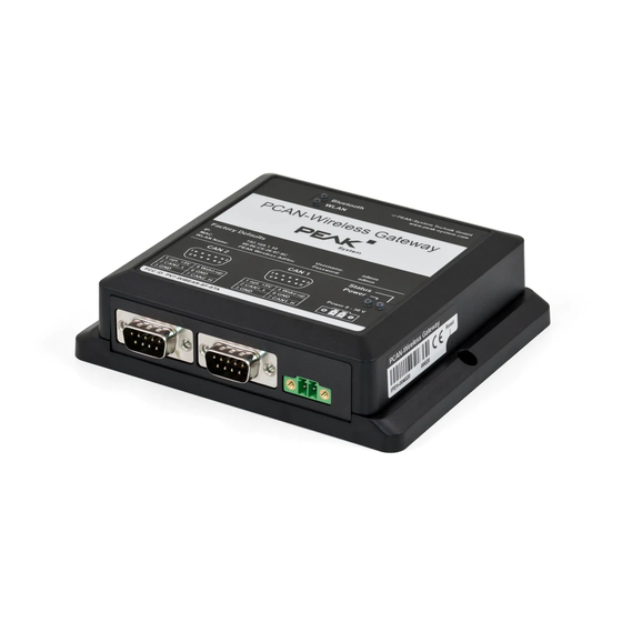
PCAN-Wireless Gateway – User Manual Connectors The PCAN-Wireless Gateway is offered as a module with two D-Sub connectors or with a Tyco automotive connector. D-Sub Connector (Industry) A High-speed CAN bus (ISO 11898-2) is connected to the 9-pin D-Sub connector. The pin assignment for CAN corresponds to the specification CiA®... - Page 9 PCAN-Wireless Gateway – User Manual Do the following to activate the voltage supply: Risk of short circuit! Solder with great care to avoid unwanted short circuits on the card. Attention! Electrostatic discharge (ESD) can damage or destroy components on the card. Take precautions to avoid ESD.
- Page 10 PCAN-Wireless Gateway – User Manual Figure 2: Position of the solder fields on the board for a 5-Volt supply at the CAN connection 5-Volt supply D-Sub connector Solder field Without With (standard) (Pin 1) CAN1 CAN2 Risk of short circuit! The 5-Volt supply is not protected separately.
-
Page 11: Automotive Connector (Tyco)
The mating connector is included in the scope of supply and consists of the components: Tyco929051-1, Tyco968473-1, and Tyco928999-1. Antenna The PCAN-Wireless Gateway is equipped with an internal chip antenna. The connection to WLAN will be established via the antenna. -
Page 12: Power Supply (Industry)
PCAN-Wireless Gateway – User Manual Power Supply (Industry) The connection for the power supply is located on the front side of the casing. The connection is done with a mating connector for fastening cable standards. The polarity is as follows: The mating connector (Phoenix Contact MC 1,5/2-STF-3,81 - 1827703) is included in the scope of supply. -
Page 13: Putting Into Operation
PCAN-Wireless Gateway – User Manual Putting into Operation The PCAN-Wireless Gateway is configured via a web interface. In the delivery state and after resetting to factory defaults, the device provides a Micro Access Point network you can connect to via WLAN. -
Page 14: Establishing The Connection
PCAN-Wireless Gateway – User Manual Open the properties of Internet Protocol Version 4 (TCP/IPv4). Make a note of the current settings in order to reset the computer later on. Select Use the following IP address. Enter an IP address in the range from 192.168.1.1 to 192.168.1.254 (but not the PCAN-Gateway's own address... - Page 15 Enter. The restricted area appears and you can start setting up the PCAN-Wireless Gateway. You can find a description of the basic configurations in the following section 3.2. Note: Afterwards reset the computers IP address to the...
-
Page 16: Basic Configuration
PCAN-Wireless Gateway – User Manual Basic Configuration Change your login data first and then set up the PCAN-Gateway connection to CAN and the WLAN network. 3.2.1 Changing Login Data Open the page Device > User Management. Change the login data on this page. Create a new username and a new password. -
Page 17: Connecting To The Wlan Network
PCAN-Wireless Gateway – User Manual 3.2.3 Connecting to the WLAN Network Accommodate the IP address data of the PCAN-Gateway to the future WLAN network. Open the page Network > WLAN. Operation Mode Infrastructured While in the form, choose Mode (Client) in order to connect with an existing WLAN network. - Page 18 PCAN-Wireless Gateway – User Manual Manual Address Assignment If the WLAN network does not provide DHCP, enter the address data that the PCAN-Gateway uses in the WLAN Network at the bottom of the page: IP address and Subnet mask. The gateway address can optionally be specified.
-
Page 19: Installing The Pcan-Gateway
PCAN-Wireless Gateway – User Manual Installing the PCAN-Gateway Do the following to connect the PCAN-Wireless Gateway to the IP network (WLAN): Mount the PCAN-Wireless Gateway at the appropriate position. Connect each of the two CAN ports with the affiliated CAN network. -
Page 20: Operation
Power supply is applied No function. Reserved for future extensions. Reset Button If the PCAN-Wireless Gateway is no longer accessible due to an incorrect configuration, the device can be reset to factory defaults using the reset button. To perform a reset, press with a paper clip for example into the small hole on the right side of the casing. -
Page 21: Wake-Up
PCAN-Wireless Gateway – User Manual Wake-Up If the PCAN-Wireless Gateway is in power-off mode (supply voltage is applied, power LED off) a wake-up signal is required so that it starts to operate. When a message is received on a CAN channel, the PCAN-Wireless Gateway turns on. -
Page 22: Configuration
PCAN-Wireless Gateway – User Manual Configuration Figure 5: Configuration Website The configuration of the device is done via a comfortable web interface. Enter the IP address of your PCAN-Gateway into the address bar of your browser. Afterwards the configuration website opens. Besides providing a... - Page 23 PCAN-Wireless Gateway – User Manual The information that is visible to non logged in users (Public Device > User Management Dashboard) can be set on the page (see section 5.6.2 on page 57). The login area can be found to the upper right of the website.
-
Page 24: Structure Of The Website
PCAN-Wireless Gateway – User Manual Structure of the Website 5.1.1 Header The header area of the website displays the product name, as well as a user defined name and description that can be set on the Device > Configuration page. This information is used to identify the device. -
Page 25: General Symbols
PCAN-Wireless Gateway – User Manual Navigating away from the current page will automatically deactivate this function too Status LED On: The status LED on the device will light up for approximately 10 seconds. This function can be used to identify the device Reboot Device: Use this link to restart the device. -
Page 26: Status
PCAN-Wireless Gateway – User Manual Status Status On the page the current device configuration is displayed. Device Information: In this box the product name, the order number, and the serial number of the device are displayed. This information can be used to uniquely identify the device. - Page 27 PCAN-Wireless Gateway – User Manual Defined Routes: Here, each message forwarding is displayed with its basic information. For each of these, the index, the status, the used transmission protocol, the source and destination, as well as the used filters are specified.
-
Page 28: Routing
Detected Devices: This table shows all PEAK-System gateways that were detected during the last network broadcast scan. If no other devices are currently in the network or no scan has been performed, this table will not be shown. -
Page 29: Manage Routes
PCAN-Wireless Gateway – User Manual 5.3.1 Manage Routes Routing > Manage Routes On the page the message forwarding instances are listed with basic information and control options. For each of these, the index, the status, the used transmission protocol, the source and destination, as well as the used filters are specified. - Page 30 PCAN-Wireless Gateway – User Manual In a Receive route the PCAN-Gateway receives data via the IP interface and forwards it to a CAN channel. The IP address is displayed in this case as "Local IP". In a Send route the data of a CAN channel is forwarded over the IP interface.
-
Page 31: Add / Edit Route
PCAN-Wireless Gateway – User Manual Routing > Add Route Add Route : This button opens the page on which you can set up a new message forwarding instance. Additional information: Each route is provided with additional information about its connection and data transfer status. This additional information can be viewed by clicking on the triangle icon located on the right edge of the route. - Page 32 PCAN-Wireless Gateway – User Manual address shown in this case is "Local IP". The configuration of the Network > WLAN local IP interface is done on the page. Send CAN > IP: In a Send route the data of a CAN channel is forwarded over the IP interface.
- Page 33 PCAN-Wireless Gateway – User Manual Select the desired device from this drop-down menu. The following IP address is automatically set to the appropriate value. If you prefer to enter the IP address yourself, select "Manual Input". IP Address: Enter the IP address (IPv4) of the destination device. It should be noted that only values from 0 to 255 may be used and certain address ranges are reserved.
- Page 34 PCAN-Wireless Gateway – User Manual error free transmission is not guaranteed. The advantage UDP has over TCP is the lower demand on performance. Note: Any combination of the IP address, port, and protocol can only be used once. Frames per Packet: This value specifies how many CAN frames are transmitted per IP packet.
- Page 35 PCAN-Wireless Gateway – User Manual User Notes: Additional information with a length of 125 characters can be Routing > entered for each route. This text is available on the page Manage Routes Finally you can create a new route with the Add Route button or save the changes after editing with the Save Settings button.
-
Page 36: Scan For Devices
Detected Devices: This table shows all PEAK-System gateways that were detected during the last network broadcast scan. If no other devices are currently in the network or no scan has been performed, this table will not be shown. -
Page 37: Filters
PCAN-Wireless Gateway – User Manual Filters Filters are used to filter CAN messages by their ID. It is possible to create up to 32 of them. Each filter can be attached to multiple Send Add Route Edit Route routes via the page... - Page 38 PCAN-Wireless Gateway – User Manual Name: While creation a name can be assign to a filter. It can be used for identification while managing the filters or attaching them to routes. Range Mask Type: This column displays the filter type ( ) and the used CAN ID mode (11- or 29 Bit).
-
Page 39: Add / Edit Filter
PCAN-Wireless Gateway – User Manual 5.4.2 Add / Edit Filter On this page you can set up a new filter. Similarly, an existing one can be edited via the form displayed. For this, the current settings are loaded into the form fields. Editing a filter is done via the page Filters >... - Page 40 PCAN-Wireless Gateway – User Manual Type Range: Range If the filter type was chosen, a lower and an upper limit have to be specified to set the range. This can be done via the slider (JavaScript support required) or with the input forms.
- Page 41 PCAN-Wireless Gateway – User Manual Acceptance Mask Acceptance Code The size of the depends on the ID mode selection above and can be 11 Bit for Standard with a range of 0 to 7FF or 29 Bit for Extended with a range of 0 to 1FFFFFFF.
-
Page 42: Network
PCAN-Wireless Gateway – User Manual Network Network page provides information about the current configu- ration of available communication interfaces. CAN Interfaces: For each CAN channel the status, the bit rate, and the setting of the Listen-Only-Mode are displayed. Network > CAN The CAN interfaces can be configured on the page. - Page 43 PCAN-Wireless Gateway – User Manual Status: The LED indicates the state of the CAN channel. LED Symbol Status Meaning Active The CAN interface is active and the error counter is lower than 96 (Error Active). Inactive The channel is inactive or sleeping.
- Page 44 PCAN-Wireless Gateway – User Manual Device > User Management In Expert mode, (See chapter 5.6.2 further detailed information is displayed. CAN Channel Configuration: Each channel is handled and configured by a separate form. Settings can be saved by clicking the Save Settings button located underneath the form.
- Page 45 PCAN-Wireless Gateway – User Manual Configuring Custom Bit Rates In Expert mode, you can create a custom bit rate and configure the Custom Bit Rate sample point. Via the checkbox, the necessary input fields for entering the register values of the CAN controller are displayed.
- Page 46 PCAN-Wireless Gateway – User Manual sum must be at least 4. Time Segment 2 is defined by Phase Segment 2. Figure 6: Bit Timing Note: When entering values the resulting transmission rate is automatically calculated in real time. If the values are incorrect, or the calculated bit rate is beyond the limits of the CAN transceiver (40 kbit/s to 1 Mbit/s), the data can not be saved.
-
Page 47: Wlan
PCAN-Wireless Gateway – User Manual 5.5.2 WLAN Network > WLAN page displays the current settings of the WLAN interface and provides options for configuration. WLAN Interface In this box the settings of the WLAN interface will be displayed. Operation mode, IP address, Subnet mask, and gateway are adjustable. - Page 48 PCAN-Wireless Gateway – User Manual Note: The Network Scan function is not available while Micro Access Point operating the device in mode. The following connection settings have to be entered manually. The WLAN LED is not active while running the device in Micro Access Point mode.
- Page 49 PCAN-Wireless Gateway – User Manual Address Settings The WLAN interface can be configured by using this form. Settings can be saved by clicking the Save Settings button located below the form. DHCP: If the IP network uses DHCP (Dynamic Host Configuration Protocol), the PCAN-Gateway IP address, Subnet mask, and gateway address are assigned automatically.
- Page 50 PCAN-Wireless Gateway – User Manual Subnet mask: The Subnet mask indicates which part of the IP address represents the network, and which part represents the device. This subdivision is achieved by filling in the (binary) Subnet mask from left to right with the number “1”. The resulting values for the individual fields are: 0, 128, 192, 224, 240, 248, 252, 254 and 255.
-
Page 51: Wlan Network Scan
PCAN-Wireless Gateway – User Manual Note: The selected region must correspond to the setting of your wireless router. Otherwise, the wireless network may not be found and no connection can be established. 5.5.3 WLAN Network Scan Infrastructured Ad-Hoc While operating the device in... -
Page 52: Device
PCAN-Wireless Gateway – User Manual Device Device page displays detailed information about your PCAN- Gateway. General Product Information: In this area, the product name, order number, and the serial number of the device are displayed. This information can be used to uniquely identify the device. -
Page 53: Device Configuration
PCAN-Wireless Gateway – User Manual 5.6.1 Device Configuration Device > Configuration On the page it is possible to assign a custom name and description to the device. In addition to that, different import and export options are available. Custom Device Name and Description: Use this form to assign a name and description to the PCAN- Gateway. - Page 54 PCAN-Wireless Gateway – User Manual Import Configuration: This form allows the importing of locally saved configuration files. After an import, all communication interfaces and device settings, as well as the routes and filters are restored. The current configuration is overwritten within that process.
- Page 55 PCAN-Wireless Gateway – User Manual Reload Default Settings: With the Reload button you can restore the device to its factory defaults. During this process the login settings, all device and communication interface settings along with existing routes will be restored to the states they were in at the time of product delivery.
- Page 56 PCAN-Wireless Gateway – User Manual JSON Interface Configuration (Expert mode only): The JSON interface is an alternative way to access the status information and configuration of the PCAN-Gateways. A specific request is then transmitted as a GET parameter of a URL and the PCAN-Gateway returns a JSON-formatted response.
-
Page 57: User Management
PCAN-Wireless Gateway – User Manual 5.6.2 User Management Device > User Management page provides options for entering new login credentials, changing and defining the display mode, and determining what information should be visible on the login page. Login Settings: Enter your current login details in the upper part of the form. In the lower part you can enter a new username and a new password. - Page 58 PCAN-Wireless Gateway – User Manual Display Mode Setting: This form provides the opportunity to change the display mode. Expert mode enables access to more detailed information and professional settings. Interpreting this information and using these features requires advanced knowledge of TCP/IP, CAN, and the message forwarding of the PCAN-Gateways.
-
Page 59: Software Update
Device as well as on the page. Current product updates can be downloaded on the PEAK-System website (www.peak-system.com). Please make sure to download the correct package for your device. Every version of the PCAN- Gateway product family has a separate download package. -
Page 60: Help
Question mark icons are located next to every page title, clicking on one will open a corresponding help page Support Support On the page you will find links to product documentation (German and English) as well as contact information of PEAK- System Technik GmbH. -
Page 61: Application Examples
PCAN-Wireless Gateway – User Manual Application Examples The PCAN-Wireless Gateway allows the connection of different CAN busses over IP networks. CAN frames are wrapped in TCP or UDP message packets and then forwarded via the IP network from one device to the other. This makes it possible for CAN networks to connect to each other over large distances. - Page 62 PCAN-Wireless Gateway – User Manual Creating a Send Route: Incoming messages from Gateway 1 are to be transferred into the WLAN network. For this, a Send route with the following values must be created. Gateway 1 > Send Route Route Direction Send: CAN >...
- Page 63 Routing > Manages deactivating or erasing one of the routes on the Routes page. Note: The putting into operation of a PCAN-Wireless Gateway Putting into Operation is described in detail in chapter 3 Detailed information concerning the creation of routes, as well as input and selection options, can be found in chapter 5.3.2...
-
Page 64: Bidirectional Data Transmission
PCAN-Wireless Gateway – User Manual Bidirectional Data Transmission For bidirectional data transmission the message traffic occurring between CAN busses A and B is to be forwarded via the WLAN network. For this two PCAN-Wireless Gateways are needed, where for each one, a Send and Receive route must be created. - Page 65 PCAN-Wireless Gateway – User Manual Gateway 1 > Send Route A Route Direction Send: CAN > IP Status Activate Channel 1 (connected to CAN bus A) IP Interface IP-Address 192.168.1.202 (address of Gateway 2) Port 50000 Protocol Gateway 1 is to accept the data packets sent via WLAN network by Gateway 2, and pass the containing CAN messages through CAN channel 1 into CAN bus A.
- Page 66 PCAN-Wireless Gateway – User Manual The Routes on Gateway 2: Gateway 2 is to accept the data packets sent via WLAN network by Gateway 1, and pass the containing CAN messages through CAN channel 2 into CAN bus B. For this, a Receive route with the following values must be created.
- Page 67 Routing > Manages Routes page. Note: The putting into operation of a PCAN-Wireless Gateway Putting into Operation is described in detail in chapter 3 Detailed information concerning the creation of routes, as well as input and selection options, can be found in chapter 5.3.2...
-
Page 68: Technical Specifications
PCAN-Wireless Gateway – User Manual Technical Specifications Connectors (IPEH-004020) 2 x D-Sub, 9-pin (Pin assignment according to specification CiA® 303-1) Power Phoenix connector 2-pin; Mating connector: Phoenix Contact MC 1,5/2-STF-3,81 - 1827703 Connectors (IPEH-004020-A) CAN & Power Automotive connector, 12-pin (Tyco1355505-1);... - Page 69 PCAN-Wireless Gateway – User Manual Wireless module WIBEAR-SF1 FCC ID: PV7-WIBEAR-SF-STA EN 300328: V.1.9.1 EN 301489-17: V2.2.1 Directive 1999/5/EC Power supply Supply voltage 8 - 30 V DC Max. current consumption 396 mA at 8 V 277 mA at 12 V...
-
Page 70: Appendix Ace Certificate
PCAN-Wireless Gateway – User Manual Appendix A CE Certificate... -
Page 71: Appendix B Dimension Drawings
PCAN-Wireless Gateway – User Manual Appendix B Dimension Drawings Figure 7: PCAN-Wireless Gateway industrial model (IPEH-004020) - Page 72 PCAN-Wireless Gateway – User Manual Figure 8: PCAN-Wireless Gateway automotive model (IPEH-004020-A) The figures don’t show the actual size of the products.
-
Page 73: Appendix C Disposal Information (Battery)
(Battery) The device and the battery it contains must not be disposed of with household waste. Remove the battery from the device for proper separate disposal. The PCAN-Wireless Gateway contains the following battery: 1 x button cell LR44 1.5 V...
Need help?
Do you have a question about the PCAN-Wireless Gateway and is the answer not in the manual?
Questions and answers