Table of Contents
Advertisement
Available languages
Available languages
Quick Links
Advertisement
Table of Contents

Related Manuals for NDS SMART-IN SM400


Summary of Contents for NDS SMART-IN SM400
- Page 1 SMART-IN ITALIANO Manuale Utente ENGLISH User Guide VALIDO PER I SEGUENTI MODELLI VALID FOR THE FOLLOWING MODELS SP400 SP600-24 SP1000I SM400 SP1500-24 SP600 SP1500I SM600 SP3000-24 SM1000 SP1000 SP2000I SP1500 SM1500 SP3000 SM600-24...
- Page 2 INSTRUCTIONS FOR THE PROPER DISPOSAL This electronic product is subject to the European Directive 2012/19 / EU. Comply with local waste disposal regulations, do not dispose of old products with normal household waste. The proper disposal of products that can no longer be used prevents potential negative consequences for the environment and for the population.
- Page 3 INDICE | INDEX 1. ISTRUZIONI SULLA SICUREZZA 2. CONTENUTO DELLA CONFEZIONE 3. DESCRIZIONE 4. STRUTTURA SMART-IN 5. INSTALLAZIONE 6. POSSIBILI INTERFERENZE 7. REQUISITI DELLE BATTERIE 8. SOSTITUZIONE DEI FUSIBILI 9. COMANDO REMOTO 10. MANUTENZIONE 11. PROTEZIONI E ALLARMI 12. CARATTERISTICHE TECNICHE 13.
-
Page 4: Istruzioni Sulla Sicurezza
• Le informazioni contenute in questo manuale sono soggette a modifiche senza preavviso. NDS Energy s.r.l. si riserva il diritto di apportare modifiche e migliorie al prodotto in qualsiasi momento senza... -
Page 5: Contenuto Della Confezione
IVT) 3. DESCRIZIONE SMART-IN è la gamma di inverter progettati e sviluppati da NDS, che si contraddistingue per qualità costruttiva e design. Progettati per garantire prestazioni elevate, massima sicurezza, affidabilità e soprattutto silenziosità operativa, importante per chi installa l’inverter all’interno dell’abitacolo. Grazie... -
Page 6: Caratteristiche Principali
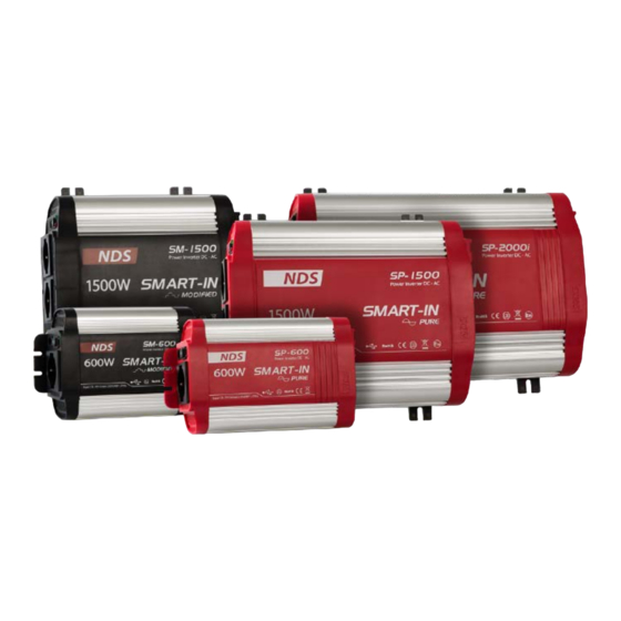
ingegneristicamente avanzate, gli inverter SMART-IN sono adatti anche ad un utilizzo professionale. La famiglia SMART-IN si compone di due linee: • SM: con uscita ad Onda Sinusoidale Modificata di colore Nero e grigio. • SP: con uscita ad Onda Sinusoidale Pura dal colore Rosso e grigio. - Page 7 4. STRUTTURA SMART-IN FRONTE Indicatori LED Verde e Rosso: Power LED Verde: inverter attivo. Fault LED Rosso: inverter in allarme (sovracorrente, sovratemperatura ecc...) Interruttore principale a tre posizioni: 0 – Inverter spento 1 – Inverter acceso 2 – Accensione / Spegnimento controllati da comando remoto Porta USB con uscita 5V e 2.1A solo per alimentare o caricare tablet, smartphone...
-
Page 8: Installazione
RETRO Co n n e t to r i d i i n g r e s s o + e – p e r l a connessione della batteria. Feritoie per ventole di raffreddamento. 5. INSTALLAZIONE... -
Page 9: Procedura Di Installazione
PROCEDURA DI INSTALLAZIONE 1. Posizionare su 0 l’interruttore di SMART-IN 2. Identificare i connettori positivo (+) e negativo (-) dedicati alla batteria. 3. Collegare il polo negativo della batteria al connettore negativo dell’inverter. 4. Installare un porta fusibile vicino al polo positivo della batteria da collegare. - Page 10 INSTALLAZIONE DEL DIFERENZIALE La presa di terra dell’inverter (connessione N.7) è destinata ad un sistema di sicurezza quale l’interruttore differenziale. 1. Predisporre l’interruttore differenziale (sensibilità Δ=30mA). 2. Collegare in ingresso all’interruttore differenziale la fase P1 e la fase P2 dell’uscita dell’inverter (i collegamenti non devono seguire un ordine particolare).
- Page 11 INSTALLAZIONE INVERTER IVT (CON CIRCUITO DI PRIORITÀ INTEGRATO) ALLA RETE 230Vac NEL CAMPER: USCITA UTENZE 230Vac INGRESSO 230Vac Collegare la spina del cavo in dotazione ad una fonte 230Vac e l’altra estremità del cavo con connettore IEC all’ingresso 230Vac dell’inverter. L’altra presa dedicata all’uscita utenze 230Vac va invece collegata al circuito i n t e r n o d e l c a m p e r .
- Page 12 6. POSSIBILI INTERFERENZE AUDIO Sistemi audio economici, se alimentati da inverter a onda modificata, possono emettere un rumore dagli altoparlanti: il sistema non riesce a filtrare il segnale ad onda modificata. Sostituire l'alimentatore del sistema audio o l'inverter con un’uscita ad onda sinusoidale pura.
-
Page 13: Sostituzione Dei Fusibili
1. Determinare la potenza complessiva in Watt delle utenze collegate simultaneamente all’inverter. Se il consumo è espresso in Ampere, moltiplicare il valore per 230V. 2. Stabilire le ore di utilizzo dell’inverter. 3. Calcolare l'energia totale in Wh (Watt ore): moltiplicare le ore di utilizzo per la potenza complessiva in Watt. - Page 14 2. È possibile usare il comando opzionale NDS RC02 o RC03, oppure realizzare un interruttore personalizzato con il cavo NDS FC01 oppure FC02 (in base al modello dell’inverter) e un interruttore esterno da almeno 24v...
- Page 15 FC01 1 2 3 4 N°PIN FUNZIONE 12v e 24v da batteria esterna collegare al pin n°2 tramite interruttore esterno per controllo remoto del dispositivo massa Per tutti i dispositivi con S/N a partire dai seguenti: • SP1500 12V S/N: 171260. •...
-
Page 16: Manutenzione
• Per i modelli di bassa potenza 400W e 600W, è disponibile un set di cavi di alimentazione con pinze di connessione ai poli della batteria. ATTENZIONE Realizzare errate connessioni a RJ11 potrebbe portare a danni irreparabili per l’inverter invalidando la garanzia. Affidarsi a personale specializzato 10. - Page 17 11. PROTEZIONI E ALLARMI Gli inverter SMART-IN sono equipaggiati con numerosi sistemi di protezione: EVENTO CAUSA RIATTIVAZIONE Tensione batteria Automatica con Allarme tensione al di sotto di 10,5V tensione batteria batteria bassa o 21,6V. Un Buzzer al di sopra di 11,2V suona.
- Page 18 È possibile installare dei fusibili addizionali secondo la tabella seguente: Modello Fusibile SM 400, SP 400 SM 600, SP 600 SM 1000, SP 1000, SP 1000-i 125A SM 1500, SP 1500, SP 1500-i 170A SP 2000-i 200A SP 3000 300A Modello Fusibile SM 600-24, SP 600-24...
-
Page 19: Caratteristiche Tecniche
12.CARATTERISTICHE TECNICHE SMART-IN Modified SM 400 Potenza nominale 400W Potenza massima 800W (pochi secondi) Tensione di uscita (RMS)/ 230Vac/50Hz ± 3 Hz Freq Uscita USB 5V @ 2.1A Tensione in Ingresso Autoconsumo 200 mA Dimensioni 184 x 140 x 71 mm SMART-IN Modified SM 600... - Page 20 SMART-IN Modified SM 1000 Potenza nominale 1000W Potenza massima 2000W (pochi secondi) Tensione di uscita (RMS)/ 230Vac/50Hz ± 3 Hz Freq Uscita USB 5V @ 2.1A Tensione in Ingresso Autoconsumo 330 mA Dimensioni 262 x 270 x 121 mm SMART-IN Modified SM 1500 Potenza nominale...
- Page 21 SMART-IN Pure SP 600 SP 600-24 Potenza nominale 600W 600W 1500W 1500W (pochi Potenza massima (pochi secondi) secondi) 230Vac/50Hz ± 230Vac/50Hz Tensione di uscita (RMS)/ Freq 3 Hz ± 3 Hz 5V @ 2.1A 5V @ 2.1A Uscita USB Tensione in Ingresso 375 mA 210 mA Autoconsumo...
- Page 22 SMART-IN pure SP 1500 SP 1500-i SP 1500-24 1500W 1500W 1500W Potenza nominale 4000W 4000W 4000W (pochi (pochi (pochi Potenza massima secondi) secondi) secondi) 230Vac/ 230Vac/ 230Vac/ Tensione di uscita 50Hz ± 3 50Hz ± 3 50Hz ± 3 (RMS)/Freq Uscita USB 5V @ 2.1A 5V @ 2.1A...
- Page 23 SMART-IN pure SP 2000-i Potenza nominale 2000W Potenza massima 6000W (pochi secondi) Tensione di uscita (RMS)/ 230Vac/50Hz ± 3 Hz Freq Uscita USB 5V @ 2.1A Tensione in Ingresso 12V / 690 mA Tempo di scambio da funzionamento a batteria a 20ms rete esterna Tempo di scambio tra rete...
- Page 24 • È sempre necessario un fusibile esterno? Tutti gli inverter NDS hanno dei fusibili interni che servono a proteggere il dispositivo e la batteria, è possibile aggiungere un fusibile a ridosso della connessione sulla batteria a 12V o 24V, questo per proteggere i cavi e l'impianto.
-
Page 25: Dichiarazione Di Conformità Ue
DICHIARAZIONE DI CONFORMITÀ UE Azienda: NDS Energy s.r.l. Indirizzo: via Giovanni Pascoli 65010 - Cappelle sul Tavo (PE) Italy Dichiara sotto la propria responsabilità che il prodotto: Nome commerciale: SMART-IN Modelli: 400W, 600W, 1000W, 1500W, 2000W, SP400, SP600, SP1000, SP1500, SP2000, SP1000i, SP1500i,... -
Page 26: Garanzia
14. GARANZIA... -
Page 28: Safety Instructions
• The information contained in this manual may be changed without notice. NDS Energy s.r.l. reserves the right to make changes and improvements to the product at any time without notice and without obligation to apply these changes to the devices... -
Page 29: Package Contents
3. DESCRIPTION SMART-IN is an inverter designed and developed by NDS, made to provide high performance, maximum safety, reliability and, above all, silent operation, important for those who install the inverter inside the passengers compartment. thanks to the adoption of some specially engineered advanced solutions, smart- in inverters are also suitable for professional use. -
Page 30: Main Features
SMART-IN family consist of two lines: • SM: with sinusoidal wave output modified in black and Gray color. • SP: with pure sinusoidal wave output from Red and Gray. The two different lines cover different powers from 400W to 3000W, with the possibility to have (for some models) the 24V input voltage. - Page 31 4. SMART-IN STRUCTURE FRONT LED Indicators Green and Red: “Power” Green LED: inverter ON “Fault” Red LED: Alarm condition (Over Load, Over Heat etc...) Main Switch with 3 positions: 0 – Inverter OFF 1 – Inverter ON 2 – Switch ON/OFF the device from remote controller USB port with 5V 1.2A output power, only to charge or supply your tablet, smartphone etc...
-
Page 32: Installation
BACK Positive and negative leisure Battery connection Cooling fan 5. INSTALLATION... -
Page 33: Installation Steps
DIFFERENTIAL SWITCH INSTALLATION The inverter earth socket is designed for a safety system such as the differential switch. To use the differential switch, follow the connection below, recommended by NDS... - Page 34 1. Prepare the differential switch with sensitivity Δ = 30mA. 2. Connect the neutral and phase of the inverter’s output P1 and P2 to the differential switch input; since it is not possible to distinguish the neutral and the output phase from the inverter, the connections do not have to follow a particular order.
- Page 35 IVT I NVE RT E R ( PR I O R I TY P C B I N T EG R AT E D ) INSTALLATION TO THE RV 230Vac: 230Vac RV APPLIANCES OUTPUT MAIN POWER SUPPLY 230Vac INPUT Connect the supplied cable plug to the 230Vac Main power supply and the other end of the cable (the IEC connector) to the inverter 230Vac input connection.
-
Page 36: Interference Problems
6. INTERFERENCE PROBLEMS AUDIO Inexpensive audio systems, when powered by modified wave inverters, may emit noise from the speakers: the system cannot filter out the modified wave signal. Replace the audio system's power supply or inverter with a pure sine wave output. TELEVISION When the inverter is operating, it can interfere with television reception on some channels, perform the... -
Page 37: Fuses Replacement
read the labels on the requirement to be operated. Usually, power consumptions shown in watts. If it is shown in amps, multiply by 110V/220V to determine the wattage. 2. Calculate the inverter operating time. 3. Calculate the total energy required in Wh (Watt hours) by multiplying the time determined above for the sum of the powers of each user. -
Page 38: Remote Control
NDS inverters can be controlled remotely by setting the selector switch to selection 2. You can use the optional NDS RC02 or RC03 control, or make your own switch with the NDS cable FC01 or FC02 (depending on the inverter model) and an external... - Page 39 FC01 1 2 3 4 PIN NUMBER FUNCTION 12v and 24v from external battery Connect at pin n°2 with external switch to remotely control the device Ground For all devices with S/n starting from the following: • SP1500 12V s/N: 171260. •...
-
Page 40: Maintenance
For the low power 400W and 600W models, a set of power cables with clamps for connection to the battery poles is available. CAUTION Making wrong connections to RJ11 could lead to irreparable damage to the inverter and invalidate the warranty. Refer to specialized technicians to do so. -
Page 41: Protection Features
11. PROTECTION FEATURES SMART-IN power inverters are equipped with numerous protection features to guarantee safe and trouble-free operation: EVENT CAUSES REACTIVATION Alerts you if the battery Automatic reactivation has become discharged with voltage up to 11,2V or Low Battery Alarm to 10.5V or lower. - Page 42 Additional fuses can be installed according to the table below: Model Fuse SM 400, SP 400 SM 600, SP 600 SM 1000, SP 1000, SP 1000-i 125A SM 1500, SP 1500, SP 1500-i 170A SP 2000-i 200A SP 3000 300A Model Fuse SM 600-24, SP 600-24...
- Page 43 12.TECHNICAL CHARACTERISTICS SMART-IN Modified SM 400 Continuous output power 400W Peak output power 800W (few seconds) Output voltage (RMS)/Freq. 230Vac/50Hz ± 3 Hz Usb output 5V @ 2.1A Input voltage Self-consumption 200 mA Size 184 x 140 x 71 mm SMART-IN Modified SM 600...
- Page 44 SMART-IN Modified SM 1000 Continuous output power 1000W Peak output power 2000W (few seconds) Output voltage (RMS)/Freq. 230Vac/50Hz ± 3 Hz Usb output 5V @ 2.1A Input voltage Self-consumption 330 mA size 262 x 270 x 121 mm SMART-IN Modified SM 1500 Continuous output power 1500W...
- Page 45 SMART-IN pure SP 600 SP 600-24 Continuous output power 600W 600W 1500W (few 1500W (few Peak output power seconds) seconds) 230Vac/50Hz ± 230Vac/50Hz Output voltage (RMS)/Freq. 3 Hz ± 3 Hz Usb output 5V @ 2.1A 5V @ 2.1A Input voltage Self-consumption 375 mA 210 mA...
- Page 46 SMART-IN pure SP 1500 SP 1500-i SP 1500-24 Continuous output 1500W 1500W 1500W power 4000W 4000W 4000W Peak output power (few (few (few seconds) seconds) seconds) 230Vac/ Output voltage 230Vac/ 230Vac/ 50Hz ± 3 (RMS)/Freq. 50Hz ± 3 Hz 50Hz ± 3 Hz Usb output 5V @ 2.1A 5V @ 2.1A...
- Page 47 SMART-IN pure SP 2000-i 2000W Continuous output power 6000W (few seconds) Peak output power 230Vac/50Hz ± 3 Hz Output voltage(RMS)/Freq. 5V @ 2.1A Usb output Input voltage 690 mA Self-consumption Switch time from battery 20ms to main AC line Switch time from main line 100ms to battery 385 x 270 x 107,5 mm...
- Page 48 • Is it always necessary to have an external fuse? All NDS inverters have internal fuses to protect the device and battery connected to them, it is good to add a fuse close to the 12V or 24V battery connection to protect the cables and the system.
- Page 49 UE DECLARATION CONFORMITY Company: NDS Energy s.r.l. Address: via Giovanni Pascoli 65010 - Cappelle sul Tavo (PE) Italy Declare under our sole responsibility that the product: Commercial Name: SMART-IN Models: 400W, 600W, 1000W, 1500W, 2000W, SP400, SP600, SP1000, SP1500, SP2000, SP1000i, SP1500i,...
-
Page 50: Warranty
14. WARRANTY... - Page 52 Tutta l’energia che ti serve all the energy you need 0002_MANB_SmartIn_ITGB03 NDS ENERGY S.R.L. Via Pascoli, 96/98 65010 Cappelle sul Tavo (Pe) Italy Tel.:+39 085 4470396 Web: www.ndsenergy.it Email: customer@ndsenergy.it LIKE US: facebook.com/ndsenergysrl...
Need help?
Do you have a question about the SMART-IN SM400 and is the answer not in the manual?
Questions and answers