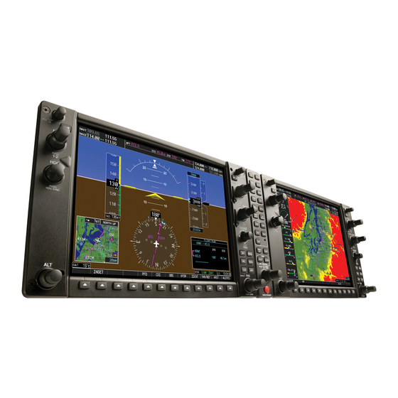
Garmin G1000 Troubleshooting
Vhf navigation system
Hide thumbs
Also See for G1000:
- Manual (724 pages) ,
- Pilot's manual (708 pages) ,
- System maintenance manual (340 pages)
Advertisement
Quick Links
1.
General
A.
This section gives the troubleshooting for the Garmin VHF Navigation System. For a general description of the Garmin
G1000 VHF Navigation System, refer to Garmin G1000 VHF Navigation System - Description and Operation.
2.
Garmin VHF Navigation System Troubleshooting
A.
Tools and Equipment
NOTE:
For the supplier publication part number and manufacturer data, refer to the Introduction - Supplier
Publication List.
(1) Tools and Equipment
•
Multimeter.
(2) Special Consumables
•
None.
(3) Reference Material
•
Garmin G1000 VHF Navigation System - Description and Operation
•
Garmin G1000 VHF Navigation System - Adjustment/Test
•
VHF Navigation Antenna - Removal/Installation
•
VHF Navigation Antenna Coupler - Removal/Installation
•
Garmin G1000 Integrated Avionics System - Adjustment/Test
•
Garmin G1000 GIA 63W Integrated Avionics Unit - Removal/Installation
•
Model 208 Wiring Diagram Manual.
B.
Do the Garmin VHF Navigation System Troubleshooting.
(1) Connect external electrical power to the airplane.
(2) Make sure that the circuit breakers given in Table 101 are engaged.
Table 101. Circuit Breakers
Component Location
No. 1 (Left) Garmin GIA 63W
Integrated Avionics Unit
No. 2 (Right) Garmin GIA 63W
Integrated Avionics Unit
(3) Refer to Chapter 34, Garmin G1000 Integrated Avionics System - Adjustment/Test G1000 Architecture Verification
Check and make sure that:
(a) The correct software and configuration has been installed.
(b) All related systems are serviceable.
(c) The LRU serial number or a version number is not dashed.
(4) Make sure the COM1, COM2, GIA1 and GIA2 have check marks (green) next to their nomenclature on the list.
(a) This indicates the LRU is serviceable.
(5) Make sure that on the System Status List the NAV1 and/or NAV2 do not show a red X .
(6) If the Garmin GIA shows an red X on the System Status page, make sure that the electrical power and ground
connections to the GIA is serviceable. Refer to the Model 208 Wiring Diagram Manual, Chapter 20, Wiring -
Maintenance Practices.
(7) If a serial number or a version number is dashed, carefully examine the electrical wiring and components as follows:
Refer to the Model 208 Wiring Diagram Manual, Chapter 20, Wiring - Maintenance Practices.
NOTE:
(a) Do a visual check of the electrical connectors and airplane electrical connectors for bent pins and pushed back
pins.
Copyright © Textron Aviation Inc.
Retain printed data for historical reference only. For future maintenance, use only current data.
GARMIN G1000 VHF NAVIGATION SYSTEM - TROUBLESHOOTING
Circuit Breaker Name
COM 1
NAV 1
COM 2
NAV 2
Serial number is not reported for the following equipment: COM1, COM2, GS1, GS2, GTX1, GTX
2 (OPT), NAV1, NAV2, AND WX500.
Model 208/208B Maintenance Manual (Rev 33)
34-56-00-1 (Rev 31)
Circuit Breaker Location
Avionics Circuit Breaker Panel
Avionics Circuit Breaker Panel
Avionics Circuit Breaker Panel
Avionics Circuit Breaker Panel
Print Date: Thu May 18 08:50:04 CDT 2023
Page 1 of 3
Advertisement

Related Manuals for Garmin G1000


Summary of Contents for Garmin G1000
- Page 1 (5) Make sure that on the System Status List the NAV1 and/or NAV2 do not show a red X . (6) If the Garmin GIA shows an red X on the System Status page, make sure that the electrical power and ground connections to the GIA is serviceable.
- Page 2 Tighten loose coaxial cable connectors as necessary. Repair or replace unserviceable coaxial cable as necessary. Interchange the left and the right Garmin GIA 63W Integrated Avionics Unit. Refer to Chapter 34, Garmin G1000 GIA 63W Integrated Avionics Unit - Removal/Installation.
- Page 3 Table 102. VHF Navigation CAS Alert Messages CAS Alert Message Potential Cause Correction Action NAV1 SERVICE – NAV1 needs The G1000 has detected a failure in 1. Replace GIA 1. Refer to Chapter service. Return unit for repair. NAV 1 receiver. 34, Garmin G1000 GIA 63W Integrated Avionics Unit - Removal/Installation.
Need help?
Do you have a question about the G1000 and is the answer not in the manual?
Questions and answers