
Related Manuals for Elettrotest XPS/T


Summary of Contents for Elettrotest XPS/T
- Page 1 XPS/T USER MANUAL Clicca qui per vedere la versione del manuale in Italiano. 07/03/2024 USER MANUAL XPS/T 62000595_06A...
- Page 2 99114513 XPS/T 30kVA 99114613 XPS/T 67kVA 99114813 This manual is written from XPS/T firmware version 10188. Please check the latest manual version at www.elettrotestspa.it To consult older manual versions, please contact our support at service@elettrotestspa.it 07/03/2024 USER MANUAL XPS/T 62000595_06A...
- Page 3 Document list: This manual is completed by a list of documents, useful to understand all the features of your XPS/T. Scan the QR-code or click on the link to directly download the documents. Documents Description Link QR-code User Manual Latest manual version...
- Page 4 Documents Description Link QR-code PSM Interface New software for remote use. PSM_Interface PS Interface Software for remote use. PS_interface 07/03/2024 USER MANUAL XPS/T 62000595_06A...
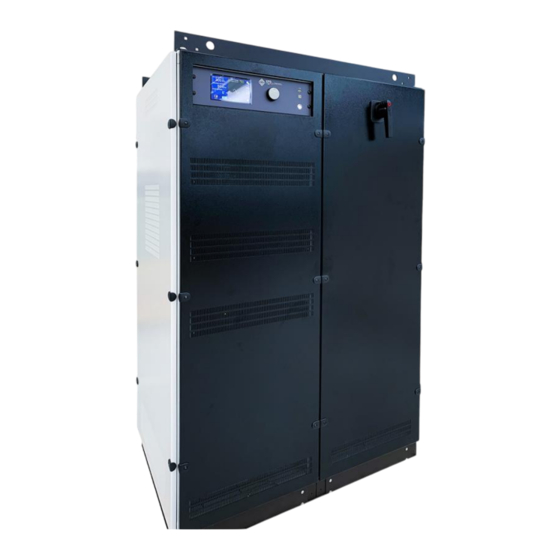
- Page 5 After sale support service@elettrotestspa.it Thank you for purchasing the XPS/T generator. XPS/T is a high-performance variable voltage generator (amplitude and frequency) in order to simulate an electrical line for tests for different application (laboratory, test line, production line) Responsability: Elettrotest disclaims any responsibility for damage to people or things caused by an improper use of its products.
- Page 6 As regards the correct connection modes, please refer to the information contained in paragraph 4. • Disconnect XPS/T from the mains before any work on the equipment and on the connected power loads. • Before touching the load or the output connector make sure that the power supply on the device has been disconnected for at least 5 minutes.
- Page 7 • the symbol (crossed-out wheeled bin) shown on the product or on the packaging and in the instruction sheet, indicates that the equipment must be disposed of separately; • in the event of illegal disposal of electrical and electronic waste, the penalties are specified by local waste disposal legislation. 07/03/2024 USER MANUAL XPS/T 62000595_06A...
-
Page 8: Table Of Contents
WHEELS MOUNT ......................... 15 3.3. MECHANICAL DRAWINGS ....................16 3.3.1. XPS/T 18KVA & XPS/T 30KVA ..................16 3.3.2. XPS/T 18KVA & XPS/T 30KVA WITH REGENERATIVE ............ 17 3.3.3. XPS/T 67KVA ......................... 18 3.3.4. XPS/T 67 KVA WITH REGENERATIVE ................19 3.4. - Page 9 ALARMS DIAGNOSIS AND REPAIRS ..................51 8.3. BASIC TROUBLESHOOTING ....................52 8.3.1. Overvoltage/Undervoltage alarms ................52 8.3.2. Overtemperature alarms ....................52 8.3.3. Inverter alarm ....................... 53 8.3.4. Max DV OUT alarm ....................... 53 8.3.5. Limit IOUT alarm ......................53 07/03/2024 USER MANUAL XPS/T 62000595_06A...
- Page 10 GUARANTEE ..........................54 10. REVISION INDEX ......................... 54 07/03/2024 USER MANUAL XPS/T 62000595_06A...
-
Page 11: Introduction
The output voltage is adjustable with continuity from zero to full scale. XPS/T can in fact provide the nominal power at various full scales and this allows the XPS/T to adapt himself to the disparate needs of the user, without having heavy limitations on the output current. -
Page 12: User Interface
0.3%. The user is also warned in case of over current obtainable by the XPS/T, or in case of high loss in the wires, that should not exceed 5% of the set voltage. -
Page 13: Models
3. MODELS The following tables show all the characteristics of all XPS/T models: XPS/T 18K36S XPS/T 30K60S XPS/T 67K90S DIMENSION / WEIGHT Height 1560 mm 1560 mm 1800 mm Height with rolls and crane support 1785 mm 1785 mm 2080 mm... -
Page 14: Technical Specifications
As can be seen from this graph, for models set in inrush operating mode (if available) the maximum output current lasts approximately 3s, after which it is reduced. 3.50 Inrush 3.00 2.50 2.00 1.50 Count. 1.00 0.50 0.00 10.0 20.0 30.0 40.0 50.0 60.0 Time (sec) 07/03/2024 USER MANUAL XPS/T 62000595_06A... -
Page 15: Wheels Mount
3.2. WHEELS MOUNT Not for all the codes of the XPS/T series the wheels are installed by default. Down here there is a list with options based on the model. Model Wheels Accessory 99114513 XPS/T 18kVA Supplied with the machine but not mounted*... -
Page 16: Mechanical Drawings
3.3. MECHANICAL DRAWINGS 3.3.1. XPS/T 18KVA & XPS/T 30KVA 1 – On/Off Switch 2 – Fans 3 – Cold air entered 5 – Rear panel for input & output connection 6 – Communications panel 07/03/2024 USER MANUAL XPS/T 62000595_06A... -
Page 17: Xps/T 18Kva & Xps/T 30Kva With Regenerative
3.3.2. XPS/T 18KVA & XPS/T 30KVA WITH REGENERATIVE 1 – On/Off Switch 2 – Fans 3 – Cold air entered 4 – Rear panel for input & output connection 5 – Communications panel 07/03/2024 USER MANUAL XPS/T 62000595_06A... -
Page 18: Xps/T 67Kva
3.3.3. XPS/T 67KVA 1 – On/Off Switch 2 – Fans 3 – Cold air entered 4 – Rear panel for input connection 5 – Rear panel for output connection 6 – Communications panel 07/03/2024 USER MANUAL XPS/T 62000595_06A... -
Page 19: Xps/T 67 Kva With Regenerative
3.3.4. XPS/T 67 KVA WITH REGENERATIVE 1 – On/Off Switch 2 – Fans 3 – Cold air entered 4 – Rear panel for input connection 5 – Rear panel for output connection 6 – Communications panel 07/03/2024 USER MANUAL XPS/T 62000595_06A... -
Page 20: Notes For Users
This interface is used for remote control via Ethernet cable RS232 Interface This interface is used for remote control via RS232 cable RS485 Interface This interface is used for remote control via RS485 cable You can select the interface from the touch panel 07/03/2024 USER MANUAL XPS/T 62000595_06A... -
Page 21: Installation
• In case connect the sense cable, 3-phase and 1-phase if the option is installed. • At the end, close the rear panel. The signal part and the power part must not be cabled together. 07/03/2024 USER MANUAL XPS/T 62000595_06A... -
Page 22: Xps/T 18Kva & Xps/T 30Kva
4.1.3. XPS/T 18KVA & XPS/T 30KVA OUT 3-PHASE OUT 1-PHASE INPUT SENSE SENSE INPUT SAFETY 19 20 10 11 12 13 14 15 L1 L2 L3 N L1 L2 L3 N PE L1 L2 L3 PE S1 S2 1-Phase OPTION... -
Page 23: Xps/T 67Kva
Output 3-Phase L1,L2,L3 Cabur ACB185 9,10,11 Output 3-Phase N Cabur ACB185 Output 3-Phase Earth Cabur TO310 14,15 Output 1-Phase Sense Cabur CB240 Output 1-Phase L Cabur ACB185 Output 1-Phase N Cabur ACB185 Output 1-Phase Earth Cabur TO310 07/03/2024 USER MANUAL XPS/T 62000595_06A... -
Page 24: Protection Device
It is recommended to use a magneto-thermal protection with type C curve according to the nominal characteristic (see section 3). 4.2.4. LINE FUSES Fuses can be used to protect power line of the XPS/T. It's recommended to use delayed fuses according to the nominal input characteristic (see section 3). 07/03/2024... -
Page 25: Internal Fuses Xps/T 18Kva & Xps/T 30Kva
4.2.5. INTERNAL FUSES XPS/T 18KVA & XPS/T 30KVA Item Name Description Size Current Type Voltage F1, F2, F3 Mainline Input 22x58 500V F4, F5, F6 Main Pre-Charge 10x38 500V F7, F8 Input Aux Transformer 10x38 500V F9, F10 Output Aux Transformer 5x20 6.3A... -
Page 26: Internal Fuses Xps/T 67Kva
4.2.6. INTERNAL FUSES XPS/T 67KVA Item Name Description Size Current Type Voltage F1, F2, F3 Mainline Input NH00 160A 500V F4, F5, F6 Input Phase 1 14x51 400V F7, F8, F9 Input Phase 2 14x51 400V F10, F11, F12 Input Phase 3... -
Page 27: Accessory Xps/T/18Kva & Xps/T/30Kva
4.2.7. ACCESSORY XPS/T/18KVA & XPS/T/30KVA Item Description FUSE 22x58 80A GG 500V FUSE 10x38 1A AM 500V FUSE 10x38 4A AM 500V FUSE 5x20 6.3A AT 250V FUSE 5x20 2.5A AT 250V FUSE 5x20 1A AT 250V USB KEY For regenerative part... -
Page 28: Wiring Diagram
4.3. WIRING DIAGRAM 4.3.1. 2 WIRE CONFIGURATION 07/03/2024 USER MANUAL XPS/T 62000595_06A... -
Page 29: Wire Configuration
4.3.2. 4 WIRE CONFIGURATION 07/03/2024 USER MANUAL XPS/T 62000595_06A... -
Page 30: Remote Control
5. REMOTE CONTROL 5.1. Control software XPS/T can be remotely controlled via RS232, RS485, TCP/IP communication according to a copyrighted free protocol or SCPI. For further details on protocol, see the specific manual. 5.2. RS232 serial cable Use a serial cable according to the standard defined in the figure below. -
Page 31: Local Operation
Apply power to the unit and turn the ON/OFF switch (see section 3.3) in position 1; in this condition the touch screen on the front panel will light up and: if the power switch (see section 3.4.1) is in position OFF, XPS/T will not start and the user must press it to start the boot process. -
Page 32: Home Page
6.2. HOME PAGE When the user turns on the XPS/T, the touchscreen shows the HOME PAGE after the startup procedure. The XPS/T starts at the factory default configuration (for the first start) or at the last stored setting. 10 11... -
Page 33: Voltage Setpoint
By clicking on the button , the “PHASE SETPOINT” button will be colored to confirm the choice and a numeric keyboard will appear to manually set the phase value. Then press “Enter” to confirm the new setting. 07/03/2024 USER MANUAL XPS/T 62000595_06A... - Page 34 Allows to access the User Settings page Remote Setting button Allows to access the Remote Settings page Operation Setting button Allows to access the Operation Settings page Limitation Settings button Allows to access the Limitation Settings page 07/03/2024 USER MANUAL XPS/T 62000595_06A...
-
Page 35: Operation Settings
Allow to change the range mode from • 3-PHASE OUTPUT MODE BUTTON • 1-PHASE Allow to change the AC/DC mode from • DC AC/DC MODE BUTTON • AC CURRENT MODE THIS MACHINE HAS ONLY COUNTINOUS MODE 07/03/2024 USER MANUAL XPS/T 62000595_06A... -
Page 36: Sense Mode
6.7.3. AC/DC The XPS/T is able to supply AC and DC voltage with the limit you can find on the chart 1.6, each phase are independent so it is possible to supply three different AC or DC voltage for each phase. -
Page 37: Ethernet Settings
6.8.1. ETHERNET settings 6.8.2. RS 232 settings 6.8.3. RS485 settings 07/03/2024 USER MANUAL XPS/T 62000595_06A... -
Page 38: User Settings
Sound Feedback button Allows to enable o disable sound feedback Brightness button Allows to change the display brightness Language button Allows to change the menu language Theme button Allows to change the interface colours 07/03/2024 USER MANUAL XPS/T 62000595_06A... -
Page 39: Output Current Limit
This limit can have big variation at high frequency This might lead to a distorted voltage signal. This mode is best for active loads (i.e. batteries or chargers) or if the load draws high peak currents. 07/03/2024 USER MANUAL XPS/T 62000595_06A... -
Page 40: Rms Limit
XXXXX.txt with a note into the header. After inserting the name and the note the XPS/T start to store every second different parameter divided by “;”, pay attention before remove the usb press the usb button. Check... -
Page 41: Operation Menu
Allows to come back to the Home page Ramp button Allows to access the ramp mode page Advanced command mode Allows to access the Advanced command mode page Alarms button Allows to access the Alarm page Only for Elettrotest use. 07/03/2024 USER MANUAL XPS/T 62000595_06A... -
Page 42: Alarms
The alarm appears when there is problem with the connection board. 6.12.2. CURRENT LIMITATION XPS/T works a control of the output current and this allows it to support for an indefinite time the output short circuit. In case of loads that absorb a current superior than the nominal one XPS/T works a limitation of the same current. -
Page 43: Bus Overvoltage & Undervoltage
The alarm appears in case of high temperature inside of XPS/T. XPS/T stops and the OVERTEMPERTURE alarm is active. 6.12.8. INVERTER ALARM In case of bad operations of the overload sections (inverter) XPS/T stops and the INVERTER alarm is active. 6.12.9. PE OVERVOLTAGE This alarm appears when there is an Overvoltage between the Output phases and earth, in this case the XPS/T stops and the PE OVERVOLTAGE alarm is active. -
Page 44: Regen Overcurrent Alarm
6.12.14. REGEN OVERCURRENT ALARM The alarm appears when the input current of the regenerative overtake the limit. The XPS/T stop and the OVERCURRENT alarm is active. 6.12.15. PFC INVERTER ALARM For future use. 6.12.16. DC/DC INVERTER ALARM For future use. -
Page 45: Ramp Function
Allows to set a Voltage and Frequency Ramp Frequency Ramp Allows to set a Frequency Ramp Voltage Ramp Allows to set a Voltage Ramp 6.13.1. Voltage/Frequency Ramp Set a voltage and frequency ramp, starting from the output present at that moment. 07/03/2024 USER MANUAL XPS/T 62000595_06A... -
Page 46: Voltage Ramp
Allows to set a final voltage value for L2 by pressing the Set Voltage L1 button (a numeric board will appear) or using the slide 6.13.2. Voltage Ramp Set a voltage ramp, starting from the output present at that moment. 07/03/2024 USER MANUAL XPS/T 62000595_06A... -
Page 47: Frequency Ramp
Allows to set the ramp duration by pressing the button (a Set Duration numeric board will appear) or using the slide Allows to set a frequency value by pressing the button (a Set Frequency numeric board will appear) or using the slide 07/03/2024 USER MANUAL XPS/T 62000595_06A... -
Page 48: Phase Ramp
Set Phase L2 (a numeric board will appear) or using the slide Allows to set a Phase value for L1 by pressing the button Set Phase L1 (a numeric board will appear) or using the slide 07/03/2024 USER MANUAL XPS/T 62000595_06A... -
Page 49: Table Of The Data Saved On The Usb
The number of days with the output active from the last Running [day] turn on of the machine The number of hours with the output active from the Running [hour] last turn on of the machine 07/03/2024 USER MANUAL XPS/T 62000595_06A... - Page 50 The total number of minutes the machine is turn on Total runnig [min] with the output active The total number of seconds the machine is turn on Total runnig [sec] with the output active 07/03/2024 USER MANUAL XPS/T 62000595_06A...
-
Page 51: Service And Maintenance
8.2. ALARMS DIAGNOSIS AND REPAIRS If one or more alarms are shown, the user must not try to repair the XPS/T by himself. Please contact ELETTROTEST S.P.A service. If the problem doesn’t solve even with the service support, the machine needs to return to the supplier (with or without guarantee). -
Page 52: Basic Troubleshooting
Broken fuse Check all the fuses. Power from EUT to XPS/T XPS/T don’t accept power from the EUT. *) Check your XPS/T plate to see the designed INPUT voltage for your device. 8.3.2. Overtemperature alarms Cause Solution Check that all the ventilation parts need to be not... -
Page 53: Inverter Alarm
8.3.3. Inverter alarm Cause Solution Power module failure XPS/T must return to the supplier Power line Check the input voltage and all the fuses. 8.3.4. Max DV OUT alarm Cause Solution Low voltage setted If a very low voltage is set, DV OUT led is generally on. - Page 54 Such document must accompany the apparatus in case of periodic verification always. 10. REVISION INDEX Elettrotest Spa is committed to a program of continuous improvement of products and information to the customer. Therefore, the company reserves the right to make changes to the documentation and specifications without notice and assumes no responsibility for any incorrect information.
- Page 55 XPS/T MANUALE UTENTE Click here to see the English version. 03/02/22 USER MANUAL XPS/T 62000595_05_...
- Page 56 99114513 XPS/T 30kVA 99114613 XPS/T 67kVA 99114813 This manual is written from XPS/T firmware version 10188. Please check the latest manual version at www.elettrotestspa.it To consult older manual versions, please contact our support at service@elettrotestspa.it 03/02/22 USER MANUAL XPS/T 62000595_05_...
- Page 57 Lista Documenti: Questo manuale è completato da un elenco di documenti utili per comprendere tutte le caratteristiche del vostro XPS/T. Scansiona il QR-code o clicca sul link per scaricare direttamente i documenti di cui hai bisogno. Documents Description Link QR-code...
- Page 58 Documents Description Link QR-code Nuovo software per la comunicazione PSM Interface PSM_Interface remota PS Interface Software per la comunicazione remota. PS_interface 03/02/22 USER MANUAL XPS/T 62000595_05_...
- Page 59 Supporto service@elettrotestspa.it Grazie per aver acquistato il generatore XPS/T. XPS/T è un generatore di tensione variabile (ampiezza e frequenza) ad alte prestazioni per simulare e testare linee elettriche per diverse applicazioni (laboratorio, linea di test, linea di produzione). Responsabilità: Elettrotest declina ogni responsabilità per danni a persone o cose causati da un uso improprio dei propri prodotti.
- Page 60 • Il dispositivo deve essere collegato all’alimentazione di rete tramite degli appositi dispositivi di protezione. • XPS/T deve essere collegato a terra tramite le apposite connessioni. Il non rispetto o l’usura di questo collegamento può portare a shock elettrico anche mortale.
- Page 61 • In caso di smaltimento abusivo dei rifiuti elettrici ed elettronici sono previste sanzioni stabilite dalle vigenti normative locali in materia di smaltimento. 03/02/22 USER MANUAL XPS/T 62000595_05_...
- Page 62 MONTAGGIO RUOTE ........................15 3.1. DISEGNI MECCANICI ......................16 3.1.1. XPS/T 18KVA & XPS/T 30KVA ..................16 3.1.2. XPS/T 18KVA & XPS/T 30KVA CON RIGENERATIVO ............17 3.1.3. XPS/T 67KVA ......................... 18 3.1.4. XPS/T 67 KVA CON RIGENERATIVO ................19 3.2.
- Page 63 RISOLUZIONE PROBLEMI BASE .................... 55 8.3.1. Allarmi di sovratensione ....................55 8.3.2. Allarmi di sovratemperatura ..................55 8.3.3. Allarme inverter ......................55 8.3.4. Allarme Max DV OUT ....................56 8.3.5. Allarme Limit IOUT ......................56 GARANZIA ..........................57 03/02/22 USER MANUAL XPS/T 62000595_05_...
- Page 64 10. REVISIONE ..........................57 03/02/22 USER MANUAL XPS/T 62000595_05_...
-
Page 65: Introduzione
0,1% con carico lineare ed a pieno carico. Il carico che l'XPS/T è in grado di pilotare può variare da una capacità pura ad una induttanza pura. La tensione di uscita è regolabile con continuità da zero a fondo scala, l'XPS/T può infatti fornire la potenza nominale a vari fondo scala e questo permette ad esso di adattarsi alle più... -
Page 66: Interfaccia Utente
1.1.3. Interfaccia utente XPS/T ha lo scopo di avere un'interfaccia facile ed intuitiva da usare. E' inoltre prevista la possibilità di un controllo da computer host, consentendo così di eseguire i test in automatico. L’XPS/T fornisce all'utente informazioni chiare sullo stato dell'uscita. La tensione impostata e la frequenza impostata vengono monitorate e la tensione di uscita viene letta con una precisione dello 0,3%. -
Page 67: Modelli
2. MODELLI La seguente tabella indica le caratteristiche tecniche di tutti i modelli XPS/T disponibili: XPS/T 18K36S XPS/T 30K60S XPS/T 67K90S DIMENSIONI / PESO Altezza 1560 mm 1560 mm 1800 mm Altezza con ruote e supporto gru 1785 mm 1785 mm... -
Page 68: Specifiche Tecniche
Da come si può vedere da questo grafico, per i modelli impostati in modalità di funzionamento inrush (se disponibile) la corrente d’uscita massima ha una durata di circa 3s, successivamente viene ridotta. 3.50 Inrush 3.00 2.50 2.00 1.50 Count. 1.00 0.50 0.00 10.0 20.0 30.0 40.0 50.0 60.0 Time (sec) 03/02/22 USER MANUAL XPS/T 62000595_05_... -
Page 69: Montaggio Ruote
3. MONTAGGIO RUOTE Non per ogni modello di XPS/T le ruote sono installate di default. Sotto si trova una lista con tutte le opzioni in base al modello. Modello Ruote Accessorio 99114513 XPS/T 18kVA Fornite con il generatore ma non montate*... -
Page 70: Disegni Meccanici
3.1. DISEGNI MECCANICI 3.1.1. XPS/T 18KVA & XPS/T 30KVA 1 – Interruttore di accensione/spegnimento 2 – Ventole 3 – Entrata aria fredda 4 – Pannello posteriore per il collegamento degli ingressi 5 – Pannello posteriore per collegamento in uscita 6 – Pannello comunicazioni... -
Page 71: Xps/T 18Kva & Xps/T 30Kva Con Rigenerativo
3.1.2. XPS/T 18KVA & XPS/T 30KVA CON RIGENERATIVO 1 – Interruttore di accensione/spegnimento 2 – Ventole 3 – Entrata aria fredda 4 – Pannello posteriore per il collegamento degli ingressi 5 – Pannello posteriore per collegamento in uscita 6 – Pannello comunicazioni... -
Page 72: Xps/T 67Kva
3.1.3. XPS/T 67KVA 1 – Interruttore di accensione/spegnimento 2 – Ventole 3 – Entrata aria fredda 4 – Pannello posteriore per il collegamento degli ingressi 5 – Pannello posteriore per collegamento in uscita 6 – Pannello comunicazioni 03/02/22 USER MANUAL XPS/T 62000595_05_... -
Page 73: Xps/T 67 Kva Con Rigenerativo
3.1.4. XPS/T 67 KVA CON RIGENERATIVO 1 – Interruttore di accensione/spegnimento 2 – Ventole 3 – Entrata aria fredda 4 – Pannello posteriore per il collegamento degli ingressi 5 – Pannello posteriore per collegamento in uscita 6 – Pannello comunicazioni... -
Page 74: Note Di Utilizzazione
Questa interfaccia viene utilizzata per il controllo remoto tramite Interfaccia RS232 cavo RS232 Questa interfaccia viene utilizzata per il controllo remoto tramite Interfaccia RS485 cavo RS485 Puoi selezionare la tipologia di interfaccia da usare tramite il touch screen. 03/02/22 USER MANUAL XPS/T 62000595_05_... -
Page 75: Installazione
Se si riscontrano danni, si prega di presentare immediatamente un reclamo al corriere. Non restituire il prodotto in fabbrica senza aver ottenuto la preventiva accettazione dell'Autorizzazione al Reso Merce (RMA) da parte di ELETTROTEST S.P.A. 4.2. Cablaggio di Potenza Togliere il pannello posteriore •... -
Page 76: Xps/T 18Kva & Xps/T 30Kva
4.2.1. XPS/T 18KVA & XPS/T 30KVA USCITA TRIFASE INGRESSO USCITA MONOFASE SENSE USCITA 3F SENSE USCITA 1F INGRESSO 3F SAFETY 19 20 10 11 12 13 14 15 L1 L2 L3 N L1 L2 L3 N PE L1 L2 L3 PE S1 S2... -
Page 77: Xps/T 67Kva
Uscita trifase L1,L2,L3 Cabur ACB185 9,10,11 Uscita trifase N Cabur ACB185 Uscita trifase Terra Cabur TO310 14,15 Uscita monofase SENSE Cabur CB240 Uscita monofase L Cabur ACB185 Uscita monofase N Cabur ACB185 Uscita monofase Terra Cabur TO310 03/02/22 USER MANUAL XPS/T 62000595_05_... -
Page 78: Dispositivi Di Protezione
4.3.1. DIAGRAMMA GENERALE Obbligatorio Le protezioni di sicurezza (Magnetotermiche e differenziali) sono obbligatorie secondo la caratteristica nominale del tuo XPS/T. Un'ulteriore protezione adeguata deve essere aggiunta quando i componenti elettrici (cavo, apparecchiature in prova – EUT) non possono supportare le prestazioni del XPS/T. -
Page 79: Fusibili Di Linea
Si consiglia di utilizzare una protezione magnetotermica con curva di tipo C in funzione della caratteristica nominale. 4.3.4. Fusibili di Linea I fusibili possono essere utilizzati per proteggere la linea di alimentazione dell'XPS/T. Si consiglia di utilizzare fusibili ritardati in base alla caratteristica nominale dell'ingresso. 03/02/22... -
Page 80: Fusibili Interni Xps/T 18Kva & Xps/T 30Kva
4.3.5. Fusibili Interni XPS/T 18KVA & XPS/T 30KVA Nome Descrizione Dimensioni Corrente Tipo Tensione F1, F2, F3 Mainline Input 22x58 500V F4, F5, F6 Main Pre-Charge 10x38 500V F7, F8 Input Aux Transformer 10x38 500V F9, F10 Output Aux Transformer 5x20 6.3A... -
Page 81: Fusibili Interni Xps/T 67Kva
500V F105, F106 F107, Input regen. part Phase 3 10x38 500V F108, F109 Il layout potrebbe essere diverso e dipende dal design del modello. 4.3.6. Fusibili Interni XPS/T 67KVA Nome Descrizione Dimensioni Corrente Tipo Tensione F1, F2, F3 Mainline Input... - Page 82 Input regen. part Phase 1 14x51 400V F103 F104, F105, Input regen. part Phase 2 14x51 400V F106 F107, F108, Input regen. part Phase 3 14x51 400V F109 Il layout potrebbe essere diverso e dipende dal design del modello. 03/02/22 USER MANUAL XPS/T 62000595_05_...
-
Page 83: Accessori Xps/T/18Kva & Xps/T/30Kva
4.3.7. Accessori XPS/T/18KVA & XPS/T/30KVA Descrizione FUSE 22x58 80A GG 500V FUSE 10x38 1A AM 500V FUSE 10x38 4A AM 500V FUSE 5x20 6.3A AT 250V FUSE 5x20 2.5A AT 250V FUSE 5x20 1A AT 250V USB KEY Per la parte Rigenerativa:... -
Page 84: Schema Di Cablaggio
4.4. SCHEMA DI CABLAGGIO 4.4.1. Configurazione 2WIRE 03/02/22 USER MANUAL XPS/T 62000595_05_... -
Page 85: Configurazione 4Wire
4.4.2. Configurazione 4WIRE 03/02/22 USER MANUAL XPS/T 62000595_05_... -
Page 86: Controllo Remoto
5. CONTROLLO REMOTO 5.1. SOFTWARE DI CONTROLLO XPS/T può essere controllato a distanza tramite comunicazione RS232, RS485, TCP/IP secondo un protocollo privo di copyright o SCPI. Per maggiori dettagli sul protocollo, vedere il manuale specifico. 5.2. CAVO SERIALE RS232 Utilizzare un cavo seriale secondo lo standard definito nella figura seguente. -
Page 87: Operazioni In Locale
Dare alimentazione all'unità e portare l'interruttore ON/OFF (vedi sezione 1.4) in posizione 1; in questa condizione si accende il touch screen del pannello frontale e: - se l'interruttore di alimentazione è in posizione OFF, l'XPS/T non si avvia e l'utente dovrà premerlo per avviare il processo di avvio. -
Page 88: Home Page
6.2. HOME PAGE Quando l'utente accende l'XPS/T, il touchscreen mostra la HOME PAGE dopo la procedura di avvio. L'XPS/T si avvia con la configurazione predefinita di fabbrica (per il primo avvio) o con l'ultima impostazione memorizzata. 10 11 Nome Descrizione... -
Page 89: Settaggio Tensione
Successivamente premere “Enter” per confermare i valori. 6.5. SETTAGGIO FASE Cliccando sul pulsante , il pulsante “SETPOINT FASE” si evidenzierà per confermare la scelta e apparirà una tastiera numerica per impostare manualmente il valore della tensione. 03/02/22 USER MANUAL XPS/T 62000595_05_... -
Page 90: Menù Impostazioni
Consente di accedere alla pagina Impostazioni utente Utente Pulsante Impostazioni Consente di accedere alla pagina Impostazioni remote Remote Pulsante Impostazioni di Consente di accedere alla pagina Impostazioni di Funzionamento funzionamento Pulsante Impostazioni Consente di accedere alla pagina Impostazioni limitazioni Limitazioni 03/02/22 USER MANUAL XPS/T 62000595_05_... -
Page 91: Impostazioni Di Funzionamento
Questa macchina dispone della solo Range “High” Consenti di cambiare la modalità dell'intervallo da: Pulsante OUTPUT MODE • Trifase • Monofase Consente di cambiare da • DC Pulsante AC/DC MODE • AC Pulsante CURRENT Questa macchina dispone della sola modalità continuous 03/02/22 USER MANUAL XPS/T 62000595_05_... -
Page 92: Sense Mode
6.6.4. AC/DC L'XPS/T è in grado di fornire tensione AC e DC con il limite riportato nella tabella dei modelli, ogni fase è indipendente quindi è possibile fornire tre diverse tensioni AC o DC per ciascuna fase. -
Page 93: Impostazioni Ethernet
6.7.1. Impostazioni ETHERNET 6.7.2. Impostazioni RS 232 6.7.3. Impostazioni RS485 03/02/22 USER MANUAL XPS/T 62000595_05_... -
Page 94: Impostazioni Utente
Pulsante Feedback Consente di abilitare o disabilitare il feedback sonoro sonoro Pulsante Luminosità Consente di modificare la luminosità del display Pulsante Lingua Consente di cambiare la lingua Pulsante Tema Consente di modificare i colori dell'interfaccia 03/02/22 USER MANUAL XPS/T 62000595_05_... -
Page 95: Impostazioni Limitazioni
Questo limite può avere grandi variazioni ad alta frequenza Ciò potrebbe causare un segnale di tensione distorto. Questa modalità è la migliore per carichi attivi (ad es. batterie o caricabatterie) o se il carico assorbe correnti di picco elevate. 03/02/22 USER MANUAL XPS/T 62000595_05_... -
Page 96: Limite Rms
Dopo aver inserito la chiavetta USB sulla connessione del pannello frontale e aver premuto il pulsante è possibile creare un nuovo file XXXXX.txt con una nota nell'intestazione. Dopo aver inserito il nome e la nota l'XPS/T inizia a memorizzare ogni secondo un parametro diverso diviso per “;”. -
Page 97: Menù Operazioni
Permette di tornare alla Home page Pulsante Rampa Consente di accedere al menu “Funzione Rampa” Modalità Comandi Consente di accedere alla pagina della modalità dei Avanzati comandi avanzati Pulsante Allarmi Consente di accedere alla pagina Allarmi Ad uso esclusivo Elettrotest. 03/02/22 USER MANUAL XPS/T 62000595_05_... -
Page 98: Allarmi
6.12.2. Allarme LIMITAZIONE CORRENTE XPS/T opera un controllo della corrente in uscita e questo gli permette di sopportare per un tempo indefinito il cortocircuito in uscita. In caso di carichi che assorbono una corrente superiore a quella nominale, l'XPS/T opera una limitazione della stessa corrente. -
Page 99: Allarme Bus Overvoltage & Undervoltage
XPS/T si ferma e mostra l'allarme. Se la tensione di rete è troppo bassa, l'XPS/T si arresta e si attiva l'allarme SOTTOTENSIONE. Se la tensione di rete è troppo alta, l'XPS/T si arresta e si attiva l'allarme di SOVRATENSIONE. 6.12.7. -
Page 100: Allarme Pfc Inverter
6.12.15. Allarme PFC INVERTER Per usi futuri. 6.12.16. Allarme INVERTER DC/DC Per usi futuri. 03/02/22 USER MANUAL XPS/T 62000595_05_... -
Page 101: Funzione Rampa
Consente di impostare una rampa di frequenza frequenza Pulsante Rampa di tensione Consente di impostare una rampa di tensione 6.13.1. Rampa di Tensione/Frequenza Imposta una rampa di tensione e di frequenza, partendo dall'uscita presente in quel momento. 03/02/22 USER MANUAL XPS/T 62000595_05_... -
Page 102: Rampa Di Tensione
Consente di impostare un valore di tensione finale per L2 Imposta Tensione L1 premendo il pulsante (apparirà una tastiera numerica) o utilizzando il cursore 6.13.2. Rampa di Tensione Imposta una rampa di tensione, partendo dall'uscita presente in quel momento. 03/02/22 USER MANUAL XPS/T 62000595_05_... -
Page 103: Rampa Di Frequenza
Consente di impostare un valore di tensione finale per L2 Imposta Tensione L1 premendo il pulsante (apparirà una tastiera numerica) o utilizzando il cursore 6.13.3. Rampa di Frequenza Imposta una rampa di frequenza, partendo dall'uscita presente in quel momento. 03/02/22 USER MANUAL XPS/T 62000595_05_... -
Page 104: Rampa Di Fase
Consente di impostare un valore di frequenza premendo Imposta Frequenza il pulsante (apparirà una tastiera numerica) o utilizzando lo slide 6.13.4. Rampa di Fase Impostare una rampa di Fase, a partire dalla fase impostata in quel momento. 03/02/22 USER MANUAL XPS/T 62000595_05_... - Page 105 Imposta fase L2 il pulsante (apparirà una tavoletta numerica) o utilizzando la diapositiva Consente di impostare un valore di Fase per L1 premendo Imposta fase L1 il pulsante (apparirà una tavoletta numerica) o utilizzando la diapositiva 03/02/22 USER MANUAL XPS/T 62000595_05_...
-
Page 106: Tabella Dei Parametri Salvati Nella Usb
Tempo in esecuzione [ore] accensione della macchina Tempo in funzionamento Il numero di minuti con l'uscita attiva dall'ultima [min] accensione della macchina Runn Tempo in Il numero di secondi con l'uscita attiva dall'ultima funzionamento [S] accensione della macchina 03/02/22 USER MANUAL XPS/T 62000595_05_... - Page 107 Tempo totale di Il numero totale di minuti di accensione della macchina funzionamento [min] con l'uscita attiva Tempo totale di Il numero totale di secondi di accensione della macchina funzionamento [S] con l'uscita attiva 03/02/22 USER MANUAL XPS/T 62000595_05_...
-
Page 108: Manutenzione E Service
8.2. RIPARAZIONE E DIAGNOSI ALLARMI Se vengono visualizzati uno o più allarmi, l'utente non deve tentare di riparare il XPS/T da solo. Si prega di contattare il service di ELETTROTEST S.P.A. Se il problema non si risolve anche con il servizio di assistenza, la macchina deve essere restituita al fornitore (con o senza garanzia). -
Page 109: Risoluzione Problemi Base
Malfunzionamento ventole Controllare il corretto funzionamento delle ventole 8.3.3. Allarme inverter Causa Soluzione Guasto del modulo di Il XPS/T/T deve essere restituito al fornitore. alimentazione Linee di potenza Controlla l’alimentazione e tutti I fusibili. 03/02/22 USER MANUAL XPS/T 62000595_05_... -
Page 110: Allarme Max Dv Out
Controllare la tensione e la corrente di uscita. La macchina è fuori calibrazione. Si prega di Calibrazione contattare il service ELETTROTEST. 8.3.5. Allarme Limit IOUT Causa Soluzione Controllare la tensione e la corrente di uscita, Sovraccarico rimuovere l'EUT e verificarne il comportamento. 03/02/22 USER MANUAL XPS/T 62000595_05_... -
Page 111: Garanzia
10. REVISIONE Elettrotest Spa è impegnata in un programma di miglioramento continuo di prodotti e informazioni per il cliente. Pertanto, la società si riserva il diritto di apportare modifiche alla documentazione e alle specifiche senza preavviso e non si assume alcuna responsabilità...
Need help?
Do you have a question about the XPS/T and is the answer not in the manual?
Questions and answers