Table of Contents
Advertisement
Quick Links
Advertisement
Table of Contents

Related Manuals for Danfoss EC-C1200-450


Summary of Contents for Danfoss EC-C1200-450
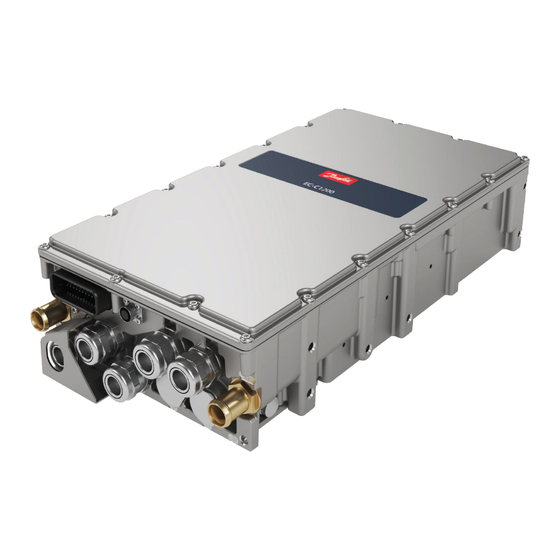
- Page 1 User Guide Electrical converter EC-C1200-450 www.danfoss.com...
- Page 2 Section updated: Service parts 0205 May 2024 Sections updated: Electrical connections, Storage, Condition monitoring during operation, 0204 Disposal of the electric device October 2023 New section added: Measuring the insulation resistance. Section updated: Electrical installation 0203 © Danfoss | August 2024 BC265735231757en-000207...
-
Page 3: Table Of Contents
Cable gland assembly and power line connection...................... 49 Cabling and wiring...................................56 High voltage connections..............................57 Low voltage connections...............................59 Operation Operation conditions..................................67 Pre-charging....................................67 Condition monitoring during operation..........................68 Maintenance Regular maintenance................................... 69 Cooling system maintenance..............................70 © Danfoss | August 2024 BC265735231757en-000207 | 3... - Page 4 User Guide EC-C1200-450 Contents Cleaning......................................70 Dismounting and disposal of the electric device Troubleshooting Aftersales Service policy....................................77 Service parts.....................................77 © Danfoss | August 2024 BC265735231757en-000207...
-
Page 5: General Information
This user guide uses illustrations as examples only. Illustrations in this user guide may not necessarily reflect all system features. Product naming convention In this user guide, the EC-C1200-450 electric converter is referred to as the electric device. The following naming convention is used to refer to electric device type code and options: •... - Page 6 User Guide EC-C1200-450 General information EC-C1200-450 options (continued) Variant Code Description Additional information Control +MC70 Motor control, current limit 70 A Converter for motor/ generator applications +MC120 Motor control, current limit 120 A Converter for motor/ generator applications +MC180 Motor control, current limit 180 A...
- Page 7 User Guide EC-C1200-450 General information EC-C1200-450 options (continued) Variant Code Description Additional information Communication CAN1939 EC-C with Standard SAE1939-communication CANopen EC-C with CANopen- communication Connections Normal connections EC-C with default HV connections +CE1 Connection extension 1 EC-C with double DC and...
- Page 8 User Guide EC-C1200-450 General information EC-C1200-450 options (continued) Variant Code Description Additional information Marine classification No marine classification +CL1 ABS American Bureau of Shipping +CL2 BV Bureau Veritas +CL3 +CL4 LR Lloyd’s Register +CL5 RINA +CL6 CCS China Classification Society...
-
Page 9: Connection Options
User Guide EC-C1200-450 General information Connection options Color coding Color Meaning Gray Cable glands for phases Cable glands for DC+ Black Cable glands for DC- © Danfoss | August 2024 BC265735231757en-000207 | 9... -
Page 10: Conformity According To Standards
Revision 5 Warranty Danfoss offers warranty against defects in workmanship and materials for its products for a period of twelve (12) months from commissioning or eighteen months (18) from delivery (Incoterms-EXW), whichever occurs first. In order for the warranty to be valid, the customer must follow the requirements of this and all related documents, especially those set out in the product installation and maintenance documents, as well as the applicable standards and regulations in force in each country. -
Page 11: Responsibility Of The Manufacturer
Rated ambient temperature °C Resistance Ω Responsibility of the manufacturer Danfoss is responsible for the safety, reliability and performance of the electric device only if: • Handling, mounting, installation, operation and maintenance are carried out by qualified and authorized service personnel. •... -
Page 12: Safety Information
It indicates a hot device that could cause burns to a person. The symbol also indicates that the device should be placed and installed so that contact with its potentially hot surface is not possible. © 12 | Danfoss | August 2024 BC265735231757en-000207... -
Page 13: Personal Protective Equipment
Use cut resistant gloves when you handle and maintain the electric device. There is a risk of cut injuries. Use protective footwear when you lift or move the electric device! Foot injuries could be caused if lifting system or lifting brackets fail. © Danfoss | August 2024 BC265735231757en-000207 | 13... -
Page 14: Safety Features
Persons with a heart pacemaker, metal implants or hearing aids must consult a doctor before they enter the following areas: © 14 | Danfoss | August 2024 BC265735231757en-000207... -
Page 15: Installation Safety
All applications where malfunction could cause injury or loss of life must be subject to a risk assessment and improve control signal protection if needed. © Danfoss | August 2024 BC265735231757en-000207 | 15... - Page 16 Do not attempt to repair the electric device. In the case of suspected fault or malfunction, contact Danfoss or Danfoss authorized service center for further assistance. When you install the electric device, make sure that the cooling system and the used coolant meet the specifications of the manufacturer.
-
Page 17: Operation Safety
The electric device uses high voltages and currents, and it has large amounts of stored electrical energy. Close attention is required to system design and electrical installation to avoid hazards in either normal operation or in the event of equipment malfunction. © Danfoss | August 2024 BC265735231757en-000207 | 17... - Page 18 User Guide EC-C1200-450 Safety information The electric device can only be used in the applications it is intended for. The rated nominal values and operational conditions are shown in the rating plate. © 18 | Danfoss | August 2024 BC265735231757en-000207...
-
Page 19: Product Overview
Note that +DC option functions together with an EC-LTS unit which is sold separately. Note also that +AFE and +UG options require an external LCL-filter unit or a transformer and LC-filter combination. © Danfoss | August 2024 BC265735231757en-000207 | 19... - Page 20 Note that this Figure shows the connections related to the +DC option and is not a general presentation of the main components. X1-connector (Low voltage connector for measurement data and control signals) X2-connector (maintenance connector) DC- / LV- EC-C unit Electric device cooling connections 2 x 20 mm © 20 | Danfoss | August 2024 BC265735231757en-000207...
-
Page 21: Motor Control (+Mc Option, Motor And Generator Control)
Electric device power connection diagram Protections and limits for options: The options for EC-C1200-450 have certain protections and limits that affect their function. The difference between protections and limits is that protections stop all high voltage functions of the electric device immediately, whereas limits only limit the functions instead of stopping them. -
Page 22: Active Front End (+Afe Option)
Active Front End (+AFE option) Active Front End is used for connecting to AC grid with regenerative power and low harmonic. In addition, it is used for bidirectional connection to AC grids. © 22 | Danfoss | August 2024 BC265735231757en-000207... -
Page 23: Microgrid (+Ug Option)
Microgrid (+UG) option is used for creating a stand-alone island grid. Microgrid application example Microgrid protections and limits Protections Hardware overcurrent trip (fixed 750A peak Short circuit trip Software overvoltage trip (configurable) Hardware overvoltage trip (fixed 1050 V © Danfoss | August 2024 BC265735231757en-000207 | 23... -
Page 24: Dcdc Converter (+Dc Option)
Power limit, LV to HV direction (boost) Current limit, HV to LV direction (buck) Current limit, LV to HV direction (boost) Overvoltage controller (HV-side) Undervoltage controller (HV-side) Overvoltage controller (LV-side) Undervoltage controller (LV-side) © 24 | Danfoss | August 2024 BC265735231757en-000207... -
Page 25: Intended Use Of The Electric Device
Operating the electric device with electric connections other than defined in the user guide. • Operating the electric device with insufficiently tightened connections or cable glands. • Operating the electric device with power cables routed against the instructions. © Danfoss | August 2024 BC265735231757en-000207 | 25... -
Page 26: System Introduction
• Storing the electric device without proper support that prevents overturning and falling. For product specific and up to date information see product data sheets at https://www.danfoss.com/. System introduction Danfoss provides electric drivetrains for applications in heavy mobile work machines, marine vessels and transportation vehicles. -
Page 27: Cooling
Rating plate example Rating plate fields Field Explanation Unit Electric device product family Electric device full type code including possible options Serial No. Serial number n ph Number of phases U nom Nominal voltage © Danfoss | August 2024 BC265735231757en-000207 | 27... -
Page 28: Tightening Torques
4 Nm Connector shield mounting screw, M4 2 Nm Cable lug mounting screws 15 Nm Grounding cable mounting screws, M8 15 Nm Cable gland (tighten from the frame of the gland) 15 Nm © 28 | Danfoss | August 2024 BC265735231757en-000207... -
Page 29: Transportation And Storage
Inspect the electric device and the package immediately upon arrival. Ensure that the rating plate data in the cover letter complies with the purchase order. All external damage in the package or in the electric device must be photographed and reported to Danfoss immediately. Lifting Use correct, adequately dimensioned lifting devices and inspect them before lifting. -
Page 30: Handling
When the device is dismounted and stored and packed for delivery, measure that there is no voltage and then install short circuit wire to the conductor rails to prevent charge from building up. © 30 | Danfoss | August 2024 BC265735231757en-000207... - Page 31 Make sure that the cabling and cooling connections are plugged and sealed before storage. Always dry the cooling circuit units before long storage. The electric device must not be subjected to any external vibrations during storage to avoid possible hidden structural damages. © Danfoss | August 2024 BC265735231757en-000207 | 31...
-
Page 32: Installation
The reference value 100 MΩ has to be exceeded at reference ambient temperature +25°C (measured with 500 V / 1 min insulation resistance test). Contact Danfoss Editron service if the reference value is not exceeded. Measuring the insulation resistance Insulation resistance testers generate lethal voltages. - Page 33 The insulation resistance is measured between terminals and the converter enclosure. When measuring the main circuit, the auxiliary circuits are grounded. When measuring the auxiliary circuits, the main circuit is grounded. Main circuit The following table lists test conditions and pass criteria for the EC-C1200-450-L and EC-C1200-450-S inverters. Test voltage Test duration Pass criteria for "-L"...
-
Page 34: Mechanical Installation
6 pcs of M8 screws. • Mounting points are shown in the Figure Location of the mounting points below. © 34 | Danfoss | August 2024 BC265735231757en-000207... - Page 35 The purpose of breather plugs is to equalize the pressure between the inside of the device enclosure and the surrounding environment. Do not remove the breather plug(s) under any circumstances. Location of the breather plug © Danfoss | August 2024 BC265735231757en-000207 | 35...
-
Page 36: Installation Procedure
Do not use excessive force when installing and removing the X1-connector because the plastic housing of the X1-connector can break. See the Figure below for more information. Always check the compatibility of the X1-connector and the counterpart. Never alter the connector in any way. © 36 | Danfoss | August 2024 BC265735231757en-000207... - Page 37 4. Connect the cooling system. See Chapter Cooling connections on page 39 or the Main dimension drawing for connection details. Make sure that there are no air pockets in the cooling channels and that © Danfoss | August 2024 BC265735231757en-000207 | 37...
- Page 38 7. Uninstall the connector shield (mechanical safety component, sheet metal part). 8. Dismount the connection box lid (power terminal cover). Connection box lid 9. Connect the power cabling. Refer to Chapter Electrical connections on page 40. 10. Install the connection box lid. © 38 | Danfoss | August 2024 BC265735231757en-000207...
-
Page 39: Cooling Connections
It is recommended to fix the hose on the coolant connection with a hose clamp or a hose clip after the protection cap has been removed. • Use water-glycol mixture with appropriate corrosion inhibitor as coolant. © Danfoss | August 2024 BC265735231757en-000207 | 39... -
Page 40: Recommended Coolants
Before you start the electrical installation, make sure that the environment is dry and free from conductive dust particles. Cable lugs are not included in the delivery. © 40 | Danfoss | August 2024 BC265735231757en-000207... - Page 41 User Guide EC-C1200-450 Installation Electrical connections X1-connector (Low voltage connector for measurement data and control signals) X2-connector (maintenance connector) DC- / LV- © Danfoss | August 2024 BC265735231757en-000207 | 41...
- Page 42 External connection box L3 connection, external L2 connection, external L1 connection, external DC- connection (+DCE) DC- connection (+DCE) DC+ connection (+DCE) DC+ connection (+DCE) Not in use Not in use Not in use © 42 | Danfoss | August 2024 BC265735231757en-000207...
- Page 43 However, with the upper connections 2-6 on the external connection box, attach the cable lugs on top of the busbars. For more information, see the figures below. Cable lug Busbar fixing bolt Busbar © Danfoss | August 2024 BC265735231757en-000207 | 43...
- Page 44 User Guide EC-C1200-450 Installation Cable lug position with +CE1 option Cable lug position in lower device connections Cable lug position with +CE1 option, top view © 44 | Danfoss | August 2024 BC265735231757en-000207...
- Page 45 9-11 as they are tightened to the correct torque at the factory. Loose connections raise the risk of overheating. Cable lug position with +CE2+DCE options Cable lug position with +CE2 and +DCE options, top view © Danfoss | August 2024 BC265735231757en-000207 | 45...
- Page 46 Converter connection box CE1 connection box Cable lug width max., L1 17.5 mm 21 mm Cable lug length L2 11.5 mm 17 mm Cable lug length max., L3 55 mm 60 mm © 46 | Danfoss | August 2024 BC265735231757en-000207...
-
Page 47: Grounding
The best grounding is achieved when the main frame of each electric device is directly connected to the ground. If this is not possible, the electric device must be grounded at least from one of the safety © Danfoss | August 2024 BC265735231757en-000207 | 47... - Page 48 All power connections must be secured with cable lugs and cable glands. EMC- shielded cable glands are used in all Danfoss products for the power connections. Make sure that the low voltage cable (control signal cable) shield is also grounded from the both ends.
-
Page 49: Cable Gland Assembly And Power Line Connection
See the manufacturer's instructions on how to install the cable glands and the cable lugs. The following instructions may not apply to every type of connection this electric device has. © Danfoss | August 2024 BC265735231757en-000207 | 49... - Page 50 Cable Washer Pflitsch BlueGlobe-series cable glands and HUBER+SUHNER Radox Elastomer S, screened, single core, automotive cables are recommended. The information below describes how to assemble screened power cables to the electric device. © 50 | Danfoss | August 2024 BC265735231757en-000207...
- Page 51 Tape 1181 or similar. Contrary to the image below and depending on the cable and the cable gland size, you can leave the length A sheath in place for the next step to help the placement of the cable gland and remove the sheath only after the next step. © Danfoss | August 2024 BC265735231757en-000207 | 51...
- Page 52 (cover) from 10 mm (distance C) from the gland bottom as shown in Figure below. Make sure that the cable gland spring is against the cable sheath (that is protected with copper tape) before cutting the braid screen. © 52 | Danfoss | August 2024 BC265735231757en-000207...
- Page 53 Remove any excess compound emerging from the sides of the cable lugs after the crimping. Verify that the cable lug is evenly compressed with clear hexagonal crimps and that no conductors are broken. See Figure below. © Danfoss | August 2024 BC265735231757en-000207 | 53...
- Page 54 If the air gap is smaller, use extra insulation shrink tube to cover the lug. 10. Screw the cable gland to the power terminals of the electric device according to instructions. Tighten the cable gland with the specified torque. © 54 | Danfoss | August 2024 BC265735231757en-000207...
- Page 55 Shrink wrap Copper tape Cable gland Cable Example of the equipment needed for the assembly Description Manufacturer's homepage Art.No./Part No. Assembly equipment Torque key and 730N/10-50 http://www.pflitsch.de (example) turnkey head SE30 http://www.pflitsch.de © Danfoss | August 2024 BC265735231757en-000207 | 55...
-
Page 56: Cabling And Wiring
Make sure that all terminal connections are tightened correctly. If the electric device drives a motor or generator, contact Danfoss if the power cable is longer than 15 m. For EMC related reasons, a filter might be needed. -
Page 57: High Voltage Connections
Cable shields must be connected to the electric device ground at both ends of the cable. All Danfoss products use EMI shielded cable glands for power connections. Wiring To ensure correct and steady operation, use EMI shielded cables for the control signals of the electric device. - Page 58 = Output power is limited by the LV-side voltage and current. LV-side voltage 600 V , HV-side voltage 750 V Product types Basic product type Nominal power [kVA] Nominal current [A EC-C1200-450+MC120+AFE120+UG120 EC-C1200-450+MC180+AFE180+UG180 EC-C1200-450+MC240+AFE240+UG240 EC-C1200-450+MC300+AFE300+UG300 EC-C1200-450+MC350+AFE350+UG350 © 58 | Danfoss | August 2024 BC265735231757en-000207...
-
Page 59: Low Voltage Connections
Always check the compatibility of the X1-connector and the counterpart. Never try to alter the connector in any way. Contact Danfoss Service if unsure. Make sure that the electric device is not in run state when removing low voltage connections or power supply. - Page 60 Pin Signal name Description VIN_N Power supply negative VIN_P Power supply positive (continuous). Typically 12-24 V, see data sheets. POWER_ON Power supply positive (from on/off key). Typically the same voltage as VIN_P. © 60 | Danfoss | August 2024 BC265735231757en-000207...
- Page 61 ) should elapse between shutting off power to the POWER_ON pin and shutting off the main power to the VIN_P pin, as indicated in the figure below. Recommended time for t is ≥ 5 s. © Danfoss | August 2024 BC265735231757en-000207 | 61...
- Page 62 Only one protocol can be chosen, and the choice should be made when placing an order for the device. It is not possible to change the protocol afterwards without sending the device back to Danfoss Editron. For more information regarding the CAN bus protocols, see user guide EC-C Software and communication manuals.
- Page 63 In case there are not enough signal ground pins available in the connector, the temperature sensor ground wires can be spliced together near the X1 connector and connected to one signal ground pin, as shown in the figure below. © Danfoss | August 2024 BC265735231757en-000207 | 63...
- Page 64 (EXC), sine (SIN) and cosine (COS) of the measurement. The resolver cable should be connected directly between the motor and the motor control inverter, as illustrated in the figure below. © 64 | Danfoss | August 2024 BC265735231757en-000207...
- Page 65 A reliable connection between the PC and the electric device can be ensured by using the Power Series Service Cable (PSSC), available from Danfoss Editron. The PSSC is a galvanically isolated and shielded USB-to-RS485 converter cable, designed for demanding environments. It is available with a 3-meter (PSSC-3M) or 10-meter cable (PSSC-10M).
- Page 66 User Guide EC-C1200-450 Installation Maintenance connector © 66 | Danfoss | August 2024 BC265735231757en-000207...
-
Page 67: Operation
The electric device must be pre-charged, see chapter on page 67. Pre-charging If the operation limits are exceeded and the electric device is damaged, please contact local Danfoss representative. Pre-charging Do the pre-charging correctly, or the high inrush current may break external electrical components of the electric device. -
Page 68: Condition Monitoring During Operation
Monitor the electric device regularly during operation to make sure of reliable operation, to foresee possible upcoming failures and to help to reach the designed lifetime of the product. © 68 | Danfoss | August 2024 BC265735231757en-000207... -
Page 69: Maintenance
Regular maintenance Do not disassemble the electric device. You can do only procedures described in this user guide. For further information contact Danfoss representative. Only trained and qualified personnel that are familiar with the relevant safety requirements can do any maintenance to the electric device. -
Page 70: Cooling System Maintenance
Weekly Monthly Yearly General Operation Abnormal phenomenon, for example noise or construction heating. If clearly increased, contact Danfoss representative. Mounting Tightness of the screws. Tighten to proper value if necessary. Applies to screws that are presented in this user guide. See Chapter Tightening torques on page 28. - Page 71 Risk of electric shock if the electric device is cleaned against instructions allowing water to go in to the electric device. Keep the electric device clean. For cleaning, use non-abrasive and non-corrosive cleaning products. Make sure that the detergent can be used for aluminum. © Danfoss | August 2024 BC265735231757en-000207 | 71...
-
Page 72: Dismounting And Disposal Of The Electric Device
11. Install the connection box lid and other parts and plug all electrical and cooling connections for longer storage. 12. Lift off the electric device according to Chapter on page 29. Lifting © 72 | Danfoss | August 2024 BC265735231757en-000207... - Page 73 Dispose of the electric device and any of its parts by appropriate means in accordance with local laws and regulations. Electric device must not be opened (excluding the connection box lid). Any attempt causes loss of warranty. Main material content for EC-C1200-450 Components Material class Weight (kg) (% wt)
- Page 74 User Guide EC-C1200-450 Dismounting and disposal of the electric device 3D exploded view © 74 | Danfoss | August 2024 BC265735231757en-000207...
-
Page 75: Troubleshooting
Do not try to repair the electric device. In the case of suspected fault or malfunction, contact Danfoss or authorized service centre for further assistance. For the reason of general safety and correct operative actions, read the instructions carefully before you start any analyses or work with the electric device. - Page 76 Fault resetting can be done with the reset signal through the fieldbus or by using maintenance connection and PowerUSER application. For more information about the fault history and fault reset, see product data sheets. © 76 | Danfoss | August 2024 BC265735231757en-000207...
-
Page 77: Aftersales
77 for available accessory and service parts. For further information, go to https://danfosseditron.zendesk.com/hc/en-gb or send email to editron.service@danfoss.com. Service parts The recommended service kits are presented below. Contact Danfoss representative for more information and purchasing. Item kit Item kit Inverter Item KIT Order number 11286812 Number... - Page 78 WASHER, D8 DIN 125 BUSBAR, OD=16, ID=8,3, L=32 BOLT. SOCKET HEAD-, M8 X 55, DIN 912, ZI SPRING.DISC-, D8, DIN 2093, 8,2 X 16 X 0,9 CABLE GLAND, M25 X 1.5, BG 225MS TRI PFLIT © 78 | Danfoss | August 2024 BC265735231757en-000207...
- Page 79 Phone: +86 21 2080 6201 Danfoss can accept no responsibility for possible errors in catalogues, brochures and other printed material. Danfoss reserves the right to alter its products without notice. This also applies to products already on order provided that such alterations can be made without subsequent changes being necessary in specifications already agreed.
Need help?
Do you have a question about the EC-C1200-450 and is the answer not in the manual?
Questions and answers