Advertisement
Quick Links
Installation Instructions
PART# QTEC66
Installing the Toggle Switch
• Make sure that the vehicle battery has been disconnected.
• The switch should be located in a place that is easy to access such as a center console, kick panel, etc.
• Connect the RED wire to a 12 volt source.
• Connect the BLACK wire to a good ground.
• Drill a 1 /2" hole where you wish to mount the switch.
• Remove the first lock ring from the shaft of the switch.
• Install switch in the hole you just drilled.
• Slide the lock ring over the switch an tighten ring so that there is no play in switch.
Routing the Wire Harness
• Make sure that you have the wire oriented so that the connectors mate. They are different, so make sure you pull the proper end into the vehicle.
• Route the wire up through the underside of the car. *Be careful to ensure that that the exhaust pipes or drive shaft do not interfere with the cable.
• Route the cables into the car. You can often open up a factory drain plug in the floor pan and snake the wire through.
• For manual transmission cars, you can also come up through the transmission shifter area. Remove the boot/seal of the transmission shifter.
• Plug the cable into the toggle switch, on the connector near the motor, align and press them together and then turn the coupling ring until it locks.
Installing the Oval Pipe
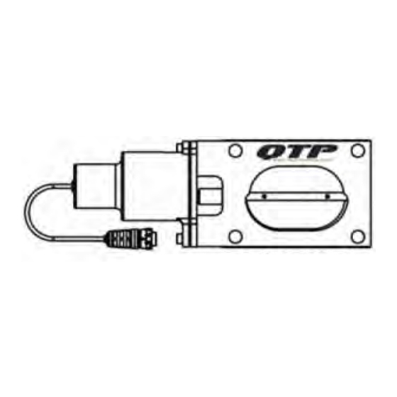
Note: The connection tube is NOT symetrical. The flange is offset on the tube to increase ground clearance.. The thicker part of the
flange MUST be oriented facing up. When bolting the valve to the flange, the QTP logo on the valve MUST also be facing up. Failure to
orient the connection tube flange and valve properly WILL result in interference between the valve and flange.
* MAKE SURE YOU POSITION THE QTEC IN THE CORRECT ANGLE SO IT DOES NOT SCRAP E THE GROUND OR HIT THE CHASSIS
OF THE CAR. LEAVE ROOM FOR ENGINE MOVEMENT. ANY DAMAGE TO THE BODY VOIDS WARRANTY. *
!
Image A
Image D
Image B
Image E
Made in the USA
Image C
Image F
Advertisement

Related Manuals for QTP QTEC66


Summary of Contents for QTP QTEC66
- Page 1 Note: The connection tube is NOT symetrical. The flange is offset on the tube to increase ground clearance.. The thicker part of the flange MUST be oriented facing up. When bolting the valve to the flange, the QTP logo on the valve MUST also be facing up. Failure to orient the connection tube flange and valve properly WILL result in interference between the valve and flange.
- Page 2 Installing the QTEC • Remove the included cap from the Y-pipe *DO NOT DISCARD THIS CAP* • Position the QTEC over the collector of the cutout pipe. Place the QTEC on the bolts on the cutout with the gasket. Coat all bolts liberally with a thread locker.
- Page 3 Warranty Quick Time Performance Inc. provides a limited warranty against defects in materials and workmanship for a period of 90 days from date of sale to the original purchaser. Upon inspection and verification of warranty, Quick Time Performance will, at its option, repair or replace products, which prove to be defective.
Need help?
Do you have a question about the QTEC66 and is the answer not in the manual?
Questions and answers