
Subscribe to Our Youtube Channel
Related Manuals for Motorola V A99 Series


Summary of Contents for Motorola V A99 Series
- Page 1 Level 1 and 2 Service Manual Product Family A99 Tri-Band Digital Wireless Telephone V.series™ 60g GSM 900/1800/1900 MHz & GPRS Technologies...
-
Page 3: Table Of Contents
1 and 2 Table of Contents Level 1 and 2 Service Manual Table of Contents 6881038B35 Table of Contents Introduction ................1 Product Identification . - Page 4 Table of Contents Product Family A99 July 23, 2001 6881038B35...
-
Page 5: Introduction
Available on a contract basis, Motorola Inc. offers comprehensive maintenance and installation programs which enable customers to meet requirements for reliable, continuous communications. To learn more about the wide range of Motorola service programs, contact your local Motorola products representative or the nearest Customer Service Manager. Product Identification Motorola products are identified by the model number on the housing. -
Page 6: Computer Program Copyrights
The Motorola products described in this manual may include Motorola computer programs stored in semiconductor memories or other media that are copyrighted with all rights reserved worldwide to Motorola. Laws in the United States and other countries preserve for Motorola, Inc. certain exclusive rights to the copyrighted... -
Page 7: Warranty Service Policy
Customer’s original units will be repaired but not refurbished as standard. Appoint- ed Motorola Service Hubs will perform warranty and non-warranty field service for level 2 (assemblies) and level 3 (limited PCB component). The Motorola HTC centers will perform level 4 (full component) repairs. -
Page 8: Parts Replacement
When ordering crystals or channel elements, specify the Motorola part number, description, crystal frequency, and operating frequency desired. When the Motorola part number of a component is not known, use the product model number or other related major assembly along with a description of the related major assembly and of the component in question. -
Page 9: Specifications
Level 1 and 2 Service Manual Specifications Specifications General Function Specification Frequency Range GSM 880-915 MHz Tx (with EGSM) 925-960 MHZ Rx Frequency Range DCS 1710-1785 MHz Tx 1805-1880 MHz Rx Frequency Range PCS 1850.2-1909.8 MHz Tx 1930.2-1989.8 MHz Rx Channel Spacing 200 kHz Channels... -
Page 10: Product Overview
Product Overview Product Family A99 Product Overview Motorola PF A99 telephones are the smallest and lightest global system for mobile communications (GSM) general packet radio service (GPRS) wireless application protocol (WAP)-enabled mobile phones currently available. The PF A99 incorpo- rates a new user interface (UI) for easier operation, allows short message service (SMS) text messaging, and includes personal information manager (PIM) function- ality. - Page 11 Level 1 and 2 Service Manual Product Overview • Supports mobile originated / mobile terminated SMS, concatenated SMS, and cell broadcast messages. • Supports GPRS, circuit switched, and SMS networks. • WAP 1.1 enabled microbrowser. • Supports SIM Toolkit (STK), Class 2. •...
- Page 12 Product Overview Product Family A99 PF A99 telephones also include a voice note recorder that allows up to 2 minutes of personal messages to be recorded. This feature has a complete set of record, playback, and management tools that make it easy to store and maintain a list of personal memos.
- Page 13 Level 1 and 2 Service Manual Product Overview event that no caller identification information is available, the Incoming Call message is displayed. User must subscribe to a caller line identification service through their service provider. Other Features Detailed descriptions of these and the other PF A99 features can be found in the appropriate PF A99 telephone user’s guide listed in the “Related Publications”...
-
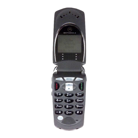
Page 14: General Operation
General Operation Product Family A99 General Operation Controls, Indicators, and Input / Output (I/O) Connections The PF A99 telephone’s controls are located on the sides of the device and on the keypad. Indicators, in the form of icons, are displayed on the LCD (see Figure 3). Service status is indicated by a tri-color light emitting diode (LED) located at the top of the phone on the right knuckle (Table 1). - Page 15 Level 1 and 2 Service Manual General Operation Service Indicator The service indicator (status light) changes color to show the user the state of the phone as shown in Table 1, below. Table 1. Service Indicator States Indication State Alternating red / green (fast) Incoming call Flashing green In service, home system...
- Page 16 General Operation Product Family A99 “Soft keys” refer to non-labeled keys that correspond to text options displayed on the screen. The left and right soft keys perform the function shown in the corners of the display. The right key will usually select an option whereas the left key will usually exit a function or return to a previous screen.
- Page 17 Level 1 and 2 Service Manual General Operation • Message Waiting Indicator. Appears when the phone receives a text mes- sage. This is a network-dependent feature. • Voice Message Waiting Indicator. Appears when a voicemail message is received. This is a network-dependent feature. •...
-
Page 18: User Interface Menu Structure
General Operation Product Family A99 User Interface Menu Structure Figure 4 shows the PF A99 telephone menu structure. 010624o Figure 4. PF A99 Menu Structure Alert Settings PF A99 telephones include up to 32 preset alert tones and vibrations that can be applied to all alert events at the same time. -
Page 19: Battery Function
Level 1 and 2 Service Manual General Operation Battery Function Battery Gauge The telephone displays a battery level indicator icon in the idle screen to indicate the battery charge level. The gauge shows four levels: 100%, 66%, 33%, and Low Battery. - Page 20 General Operation Product Family A99 July 23, 2001 6881038B35...
-
Page 21: Tools And Test Equipment
GSM / DCS Test SIM Used to enable manual test mode 1. To order in North America, contact Motorola Aftermarket and Accessories Division (AAD) at (800) 422-4210 or FAX (800) 622-6210; Internationally, AAD can be reached by calling (847) 538-8023 or faxing (847) 576-3023. -
Page 22: Disassembly
Disassembly Product Family A99 Disassembly The procedures in this section provide instructions for the disassembly of a PF A99 telephone. Tools and equipment used for the phone are listed in Table 2, preceding. Many of the integrated devices used in this equipment are vulnerable to damage from electrostatic discharge (ESD). - Page 23 Level 1 and 2 Service Manual Disassembly Lift the battery housing completely off the phone. Lift the end of the battery and remove it completely. See Figure 6. BATTERY 010626o Figure 6. Removing the battery There is a danger of explosion if the Lithium Ion battery is replaced incorrectly. Replace only with the same type of battery or equivalent as recommended by the battery manufacturer.
-
Page 24: Removing And Replacing The Subscriber Identity Module (Sim)
Disassembly Product Family A99 Removing and Replacing the Subscriber Identity Module (SIM) Remove the battery housing and battery as described in the procedures. SIM HOLDER 010627o Figure 7. Removing the SIM Slide the SIM holder down (away from the antenna) to unlock and rotate to open as shown in Figure 7. -
Page 25: Removing And Replacing The Antenna
Level 1 and 2 Service Manual Disassembly Removing and Replacing the Antenna Remove the battery housing and battery as described in the procedures. By hand, rotate the antenna counterclockwise until loose. See Figure 8. ANTENNA 010628o Figure 8. Removing the antenna When the antenna threads are completely disengaged, pull the antenna straight out of the phone to remove. - Page 26 Disassembly Product Family A99 Using a Torx driver with a T-6 bit, remove the 2 knuckle screws and 2 transceiver screws from the rear chassis assembly. See Figure 9. KNUCKLE SCREWS TRANSCEIVER SCREWS 010629o Figure 9. Removing the rear chassis assembly screws Locate the 2 housing catches on the sides of the phone as shown in Figure 10.
- Page 27 Level 1 and 2 Service Manual Disassembly Lift the rear chassis assembly away from the front housing to remove. HOUSING CATCH REAR CHASSIS ASSEMBLY DISASSEMBLY TOOL FRONT HOUSING 010630o Figure 10. Removing the rear chassis assembly To replace, carefully align rear chassis assembly with the front housing, then press the rear chassis assembly down until the 2 housing catches engage with the corresponding openings on the rear chassis assembly.
-
Page 28: Removing And Replacing The Transceiver Board Assembly
Disassembly Product Family A99 Removing and Replacing the Transceiver Board Assembly This product contains static-sensitive devices. Use anti-static handling procedures to prevent electrostatic discharge (ESD) and component damage. Remove the battery housing, battery, antenna, and rear chassis assembly as described in the procedures The flexible printed cable (FPC) (flex) is easily damaged. - Page 29 Level 1 and 2 Service Manual Disassembly Lift the transceiver board assembly from the front housing. See Figure 12. DISASSEMBLY TOOL FRONT HOUSING SPACER KEYBOARD TRANSCEIVER BOARD GASKET ASSEMBLY ASSEMBLY 010632o Figure 12. Removing the transceiver board assembly To replace, insert the transceiver board assembly into the front housing with the flex connector on top.
-
Page 30: Removing And Replacing The Volume / Smart And Voice Buttons
Disassembly Product Family A99 Removing and Replacing the Volume / Smart and Voice Buttons Remove battery housing, battery, antenna, rear chassis assembly, and trans- ceiver board assembly as described in the procedures. Using the plastic tweezers, lift the volume / smart buttons and the voice button from the transceiver board assembly. - Page 31 Level 1 and 2 Service Manual Disassembly TRANSCEIVER BOARD ASSEMBLY MICROPHONE GROMMET PLASTIC TWEEZERS MICROPHONE 010634o Figure 14. Removing the microphone Using the plastic tweezers, carefully lift the microphone grommet from the microphone as shown in Figure 14. Again using the plastic tweezers, pull the microphone straight out of its socket on the transceiver board.
-
Page 32: Removing And Replacing The Spacer Gasket
Disassembly Product Family A99 Removing and Replacing the Spacer Gasket Remove battery housing, battery, antenna, rear chassis assembly, and trans- ceiver board assembly as described in the procedures. Using the disassembly tool, lift the spacer gasket completely from the keyboard assembly. -
Page 33: Removing And Replacing The Keyboard Assembly
Level 1 and 2 Service Manual Disassembly Removing and Replacing the Keyboard Assembly Remove battery housing, battery, antenna, rear chassis assembly, transceiver board assembly, and spacer gasket as described in the procedures. Using the disassembly tool, carefully lift the keyboard assembly from the front housing. -
Page 34: Removing And Replacing The Keypad
Disassembly Product Family A99 Removing and Replacing the Keypad Remove the battery housing, battery, antenna, rear chassis assembly, trans- ceiver board assembly, spacer gasket, and keyboard assembly as described in the procedures. Lift the keypad from the front housing as shown in Figure 17. KEYPAD DISASSEMBLY TOOL FRONT HOUSING... -
Page 35: Removing And Replacing The Flip Assembly
Level 1 and 2 Service Manual Disassembly Removing and Replacing the Flip Assembly Remove the battery housing, battery, antenna, rear chassis assembly, trans- ceiver board, spacer gasket, keyboard assembly, and keypad as described in the procedures. The flex is fragile and easily damaged. Be very careful when passing the flex through the front housing opening. - Page 36 Disassembly Product Family A99 To replace, route the flex through the front housing opening and press the front housing firmly onto the knuckle posts. Be sure the front housing is flat against the flip assembly. Replace the keypad, keyboard assembly, spacer gasket, transceiver board assembly, rear chassis assembly, antenna, battery, and battery housing as described in the procedures.
-
Page 37: Subscriber Identity Module (Sim) And Identification
The Mechanical Serial Number (MSN) is an individual unit identity number and remains with the unit throughout the life of the unit. The MSN can be used to log and track a unit on Motorola's Service Center Database. The MSN is divided into 4 sections as shown in Figure 19. - Page 38 Subscriber Identity Module (SIM) and Identification Product Family A99 International Mobile Station Equipment Identity (IMEI) The International Mobile station Equipment Identity (IMEI) number is an individ- ual number unique to the PCB and is stored within the unit's memory. The following diagram illustrates the various parts of this number.
-
Page 39: Troubleshooting
Troubleshooting Troubleshooting Manual Test Mode Motorola PF A99 telephones are equipped with a manual test mode capability. This allows service personnel to verify functionality and perform fault isolation by entering keypad commands. To enter the manual test command mode, a GSM / DCS test SIM must be used. - Page 40 Troubleshooting Product Family A99 Table 3. Manual Test Commands (Continued) Key Sequence Test Function/Name Remarks 5*0*8 Set audio level 8 5*0*9 Set audio level 9 5*0*10 Set audio level 10 5*0*11 Set audio level 11 5*0*12 Set audio level 12 5*0*13 Set audio level 13 5*0*14...
-
Page 41: Troubleshooting Chart
Level 1 and 2 Service Manual Troubleshooting Troubleshooting Chart Table 4. PF A99 Telephone: Level 1 and 2 Troubleshooting Chart SYMPTOM PROBABLE CAUSE VERIFICATION AND REMEDY 1. Telephone will not turn on or stay on. a) Battery either discharged or Measure battery voltage across a 50 ohm (>1 defective. - Page 42 Troubleshooting Product Family A99 Table 4. PF A99 Telephone: Level 1 and 2 Troubleshooting Chart (Continued) SYMPTOM PROBABLE CAUSE VERIFICATION AND REMEDY 4. Incoming call alert transducer audio Faulty transceiver board assembly. Replace the transceiver board assembly (refer distorted or volume is too low. to 1c).
-
Page 43: Programming: Software Upgrade And Flexing
Level 1 and 2 Service Manual Troubleshooting Table 4. PF A99 Telephone: Level 1 and 2 Troubleshooting Chart (Continued) SYMPTOM PROBABLE CAUSE VERIFICATION AND REMEDY 8. Phone does not sense when flip is a) Flip assembly defective. Temporarily replace the flip assembly with a opened or closed (usually indicated by known good assembly. - Page 44 Troubleshooting Product Family A99 July 23, 2001 6881038B35...
-
Page 45: Part Number Charts
Level 1 and 2 Service Manual Part Number Charts Part Number Charts The following charts are provided as a reference for the parts associated with PF A99 telephones. Related Publications Motorola V.series™ 60g Wireless Phone Reference Guide, English 6809435A89 6881038B35 July 23, 2001... -
Page 46: Exploded View Diagram
Part Number Charts Product Family A99 Exploded View Diagram 010642o Figure 21. Exploded view diagram July 23, 2001 6881038B35... -
Page 47: Exploded View Parts List
Level 1 and 2 Service Manual Part Number Charts Exploded View Parts List Table 5. Exploded View Parts List Item Motorola Part Item Motorola Part Description Description Number Number Number Number 1587623K08 Front housing See Table 7 Battery housing 0187969K03... -
Page 48: Model-Dependent Part Numbers
Part Number Charts Product Family A99 Model-dependent Part Numbers Table 6. Model-dependent Part Numbers Item Part Description Part Number Number Keypad, English 3887961K02 Keypad, Simple Chinese 3887961K03 Keypad, Complex Chinese 3887961K04 Accessories Table 7. Accessories Part Description Part Number Battery, slim, Li Ion, 500 mAh SNN5717 Battery, high performance, Li Ion, 800 mAh SNN5705... -
Page 49: Index
1 and 2 Index Level 1 and 2 Service Manual Index 6881038B35 Index identification 33 international mobile station equipment identity 34 mechanical serial number 33 alert setting indicator 13 product 1 alert settings 14 IMEI 34 antenna, removing and replacing 21 in use indicator 12 indicators alert setting 13... - Page 50 Index Product Family A99 part numbers serial number accessories 44 mechanical 33 parts 41 service manual exploded view diagram 42 about 2 exploded view parts list 43 revisions 3 product scope 2 changes 1 service policy 3 identification 1 customer support 4 names 1 out of box failure 3 publications, related 41...
- Page 52 MOTOROLA, the Stylized M Logo, and all other trademarks indicated as such herein are trademarks of Motorola, Inc. ® Reg. U.S. Pat. & Tm. Off. TrueSync and Starfish are registered trademarks of Starfish, Inc., a wholly owned independent subsidiary of Motorola, Inc.
Need help?
Do you have a question about the V A99 Series and is the answer not in the manual?
Questions and answers