Advertisement
Quick Links
Advertisement

Related Manuals for DTI Winco ULPSS12H2W/E


Summary of Contents for DTI Winco ULPSS12H2W/E
- Page 1 PACKAGED STANDBY SYSTEM INSTALLATION AND OPERATORS MANUAL ULPSS12H2W/E 11075-00 60706-209...
- Page 2 SAVE THESE INSTRUCTIONS PROPER USE AND This manual contains important instructions that INSTALLATION should be followed during installation and main- tenance of the generator and batteries. Read You must be sure your new engine generator set is: and understand all instructions in the manual * Properly serviced before starting.
- Page 3 SAFETY INFORMATION 2. FIRE HAZARD Natural gas and L.P. present a hazard of possible explosion and/or fi re. This generator set has been designed and manu- a. Do not refuel when the engine is running or factured to allow safe, reliable performance. Poor hot.
- Page 4 e. Always avoid hot muffl ers, exhaust manifolds, These packaged standby systems consist ot two and engine parts. They can cause severe major components: burns instantly. f. Installing a generator set is not a “Do-it-your- 1) AUTOMATIC TRANSFER SWITCH self” project. Consult a qualifi ed, licensed elec- trician or contractor.
- Page 5 SPECIFICATIONS **** CAUTION **** These units are shipped with oil. Be sure to check GENERATOR oil levels before operating. See engine manufactur- er’s instruction manual for recommended oil require- MODEL WATTS* VOLTS AMPS HZ PH RPM ments before initial starting. PSS12 12000 120/240...
- Page 6 ENGINE GENERATOR SET MOUNTING These fuel pressures are critical; failure to provide the proper pressure can cause many problems rang- ing from a unit that will not start to causing damage WARNING - Personal Injury to the fuel system. The enclosures on these units can become very These units are normally tested on Natural Gas and hot adjacent to the exhaust areas.
- Page 7 A low pressure regulator is installed to further reduce ****************** the fuel pressure to the required four (4) to six (6) oz. ***** WARNING ***** operating pressure. This low pressure regulator ****************** must be at least 10 feet from the engine gen- PERSONAL DANGER - Do not use galvanized pipe erator set, any closer installation will require a in fuel line runs.
- Page 8 Shown below is a diagram of a natural gas (NG) Natural Gas installation. REF # UNIT OFF 2 PSI 7-11 IN 7-11 IN 4-6 OZ 4-6 OZ STARTING 2 PSI 7-11 IN 7-11 IN 4-6 OZ 4-6 OZ NO LOAD 2 PSI 7-11 IN 7-11 IN...
- Page 9 When installing or replacing batteries, use the proper DANGER - Explosive Fire Risk group/size starting battery. The battery should be a Maintenance Free lead acid design. Deep cycle * Never smoke when near batteries. batteries will not work for this application. * Do not cause a fl...
- Page 10 11075-00 60706-209...
- Page 11 CONNECTING THE BATTERY CHARGER AC ELECTRICAL CONNECTIONS A two-stage battery tender is provided on all PSS series generators. This battery tender charges at a rate of 750 mA until the battery is fully charged NOTICE - CLASS 1 WIRING METHODS ARE TO and then automatically switches to a 13.2 VDC fl...
- Page 12 The last two wires you will install are the DC control ****************** leads (14 or 16 gauge) for the start circuit in the ATS. ***** WARNING ***** These last two connections will be discussed later in ****************** more detail. A service disconnect must be installed in front of the WINCO UL ATS (ASCO 165) ATS panel as the ATS is not service enterance rated.
- Page 13 START UP PROCEDURE Engine Generator Set only WIRE # PURPOSE RECOMMENDED COLOR The engine control module (ECM) is manufactured # 23 Start Black by Deep Sea Electronics. Model 3110 is used on Battery Negative White this engine generator set. See picture below. Ad- ditional information on the DSE 3110 is on pages 14 through 17.
- Page 14 1. Turn on the preferred source (utility) circuit Transfer Switch does not transfer the load to the breaker. The utility source acceptable light should generator set. The Transfer Switch on utility (pre- now come on as well as the transfer switch on utility ferred source) light stays on.
- Page 15 In order to set and test the exercise circuit the DSE 3110 ENGINE CONTROL engine control module must be set in the auto mode. PROTECTIONS When an alarm is present, the Common alarm LED SETTING THE EXERCISER CIRCUIT if confi gured will illuminate. The LCD display will show an icon to indicate the fault.
- Page 16 DSE 3110 CONTROL STOP/RESET (Red Button) This button places the module into its “Stop/ Reset” mode. This will clear any alarm conditions for which the triggering criteria have been removed. If the engine is running and the module is in Stop mode, the module will automatically instruct the changeover device to unload the generator.
- Page 17 FRONT PANEL CONFIGURATION This confi guration mode allows the operator limited customizing of the way the module operates. Use the module’s navigation buttons to traverse the menu and make value changes to the parameters. 1. ACCEPT button. 2. NEXT PAGE button. 3.
- Page 18 DSE 3110 CONTROL FAULT CODES DESCRIPTION Auxiliary inputs can be user confi gured and will display AUXILIARY INPUTS the message as written by the user. The engine has not fi red after the preset number of start FAIL TO START attempts The module has detected a condition that indicates that the engine is running when it has been instructed to stop.
- Page 19 PREVENTIVE MAINTENANCE LOG MAINTENANCE DATE WORK PERFORMED Reasonable care in preventive maintenance will insure high reliability and a long life for the engine generator set and Automatic Transfer Switch. ***************** ***** WARNING ***** ***************** When performing any type of maintenance on this equipment make sure the selector switch on the generator is in the off position.
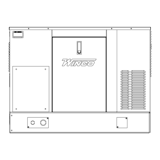
- Page 20 ENGINE GENERATOR SET LAYOUT ULPSS12H2W/E 11075-00 60706-209...
- Page 21 11075-00 60706-209...
- Page 22 ENGINE CRANKS BUT WILL NOT START TROUBLESHOOTING TABLES 1. Improper fuel pressure being delivered to unit. 2. Fuel supply shut off. 3. Fuel supply empty. ******************** 4. Defective spark plug. ****** WARNING ****** 5. Defective engine ignition module. ******************** 6. Dirty air cleaner fi lter. 7.
- Page 23 11075-00 60706-209...
- Page 24 12 MONTH LIMITED WARRANTY WINCO, Incorporated warrants to the original purchaser for 12 months or 1000 hours which ever occurs fi rst, that goods manufactured or supplied by it will be free from de- fects in workmanship and material, provided such goods are installed, operated and maintained in accordance with WINCO written instructions.
Need help?
Do you have a question about the Winco ULPSS12H2W/E and is the answer not in the manual?
Questions and answers