
Related Manuals for DTI WINCO PSS15B2W/A


Summary of Contents for DTI WINCO PSS15B2W/A
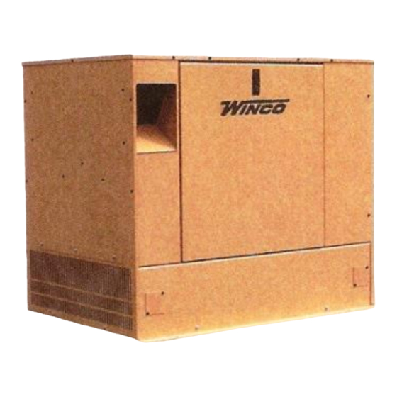
- Page 1 PACKAGED STANDBY SYSTEM INSTALLATION AND OPERATORS MANUAL PSS15B2W/A Engine Generator Set...
-
Page 2: Table Of Contents
Read and understand all instructions in the PROPER USE AND INSTALLATION manual before starting and operating the generator set. You must be sure your new engine generator set is: * Properly serviced before starting * Operated in a well ventilated area USING THIS MANUAL * Properly exhausted and gases safely dispersed * Wired by a qualified electrician... -
Page 3: Guide To Product Safety
SAFETY INFORMATION before refueling. Keep fuel containers out of reach of children. This engine generator set has been designed and Do not smoke or use open flame near the manufactured to allow safe, reliable performance. generator set or fuel tank. Poor maintenance, improper or careless use can Keep a fire extinguisher nearby and know its result in potential deadly hazards;... -
Page 4: Basic Information
TESTING POLICY: UL Automatic Transfer Switch Sizes UNIT LINE SIDE GENERATOR Before any generator is shipped from the factory, it is CONTACTOR SIDE CONTACTOR fully checked for performance. The generator is loaded to its full capacity, and the voltage, current, and frequency 100 AMPS 100 AMPS PSS15B2W/A... -
Page 5: Preparing The Unit
“Concealed Damage” is understood to mean damage to FUEL CONSUMPTION the contents of a package which is not evident at the time of delivery by the carrier, but which is discovered later. L.P. VAPOR The carrier or carriers are responsible for merchandise 1000 BTU/CU FT 2520 BTU/CUFT MODEL... -
Page 6: Fuel Installation
************* ENGINE GENERATOR SET MOUNTING ***** WARNING **** ************* The unit’s main frame should be bolted solid to a four to FIRE HAZARD - All fuel runs should be installed by a six inch thick cement pad. The engine-generator is licensed fuel supplier. -
Page 7: Vapor Fuel Pressure Tables
************* ***** WARNING **** ************* PERSONAL DANGER - Do not use galvanized pipe in fuel line runs. The galvanized coating can become eroded and flake off, causing possible obstructions in the regulator or fuel valve. The results could range from inoperative engine start to hazardous fuel leaks. -
Page 8: Lubrication
Observe polarities: connect the positive (+) battery terminal to the (+) cable from the control panel; the negative (-) battery terminal is connected to the negative cable (ground) from the engine generator assembly. All connections must be clean and tight. Check the electrolyte (fluid) in the battery periodically to be sure it is above the plates. -
Page 9: Ac Electrical Connections
All power leads from the generator to the A.T.S. must The Automatic Transfer Switch connects the load (lights, be sized to handle rated generator output amperage at a furnace, outlets, etc.) to the normal power line during minimum, the type of wire you use will determine the standby. -
Page 10: Dc Electrical Connections
************* ASCO 300 UL SWITCH ***** WARNING ***** Your DC connection points in the ASCO UL ATS are ************* terminals “14” and “15” .Depending on the size of the A service disconnect must be installed in front of the switch they are located in differnt locations. See below A.T.S. -
Page 11: Troubleshooting Information
The restoration of line power also sends a stop signal to PROCEDURE the engine generator set. This stop signal will activate a cool down timer circuit. The engine generator will shut Engine Generator Set only down 90 seconds later. The UL switches will have an Move the selector switch on the engine generator to the additional cool down delay built into the switch of as long “RUN”... - Page 12 Defective spark plug. PREVENTIVE MAINTENANCE Defective engine ignition module. Dirty air cleaner filter. Reasonable care in preventive maintenance will insure Defective fuel solenoid valve. high reliability and a long life for the engine generator set Low voltage from battery to fuel solenoid, must and the Automatic Transfer Switch.
-
Page 13: Wiring Diagram
4190-00 PAGE 11 60706-169... -
Page 14: Ac & Dc Generator Schematic
60706-169 PAGE 12 4190-00... -
Page 15: Asco 165 Dc Wiring
GENERATOR LAYOUT 4190-00 PAGE 13 60706-169... - Page 16 WINCO, Incorporated warrants to the original purchaser for 12 months that goods manufactured or supplied by it will be free from defects in workmanship and material, provided such goods are installed, operated and maintained in accordance with Winco written instructions. WINCO’s sole liability, and Purchaser’s sole remedy for a failure under this warranty, shall be limited to the repair of the product.
Need help?
Do you have a question about the WINCO PSS15B2W/A and is the answer not in the manual?
Questions and answers