Allied 395 Assembly/Operators/Parts Manual
Hide thumbs
Also See for 395:
- Operator and parts manual (36 pages) ,
- Assembly and parts manual (28 pages)
Table of Contents
Advertisement
Quick Links
Advertisement
Table of Contents

Subscribe to Our Youtube Channel
Related Manuals for Allied 395


Summary of Contents for Allied 395
- Page 2 WARRANTY REGISTRATION AND POLICY Buhler Manufacturing products are warranted for a period of twelve (12) months from original date of purchase, by original purchaser, to be free from defects in material and workmanship under correct, normal agricultural use and proper applications. Buhler Manufacturing’s obligations under this warranty shall be limited to the repair or exchange, at Buhler Manufacturing’s option, of any Buhler Manufacturing product or part which proves to be defective as provided.
-
Page 3: Table Of Contents
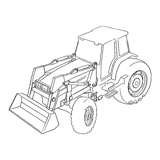
Hydraulic Farm Loader Operator’s Manual Table of Contents Section Description Page Warranty Registration and Policy........Table of Contents ............Loader Specification Chart .......... 2 Introduction Torque Chart ............... 2 Pre-delivery Check List ..........3 Loader Identification Diagram ........3 Identification Hydraulic Hose Kit Identification Diagrams .... -
Page 4: Torque Chart
Dealer Pre-delivery Check List Before delivering this equipment please complete the following check list. 1. The loader has been installed using the appropriate mounting kit for the tractor and loader. 2. The hydraulic system installed is appropriate for the tractor and loader. 3. -
Page 5: Hydraulic Hose Kit Identification Diagrams
Hydraulic ( Hose Kit ) Identification Diagrams HOSE KIT "A" Loader powered by the tractor remotes "3". Consists of four hoses "1" leading from loader tubing "2" to tractor remote couplers"3". HOSE KIT "B" Loader operated by an external OC or CC valve "3"... -
Page 6: Important Precautions
IMPORTANT PRECAUTIONS DANGER WARNING To prevent serious injury or death: To prevent serious injury or death: Do not lift, carry or allow anyone to ride on Stay away from power lines and cables. or work from any portion of loader. Electrocution can occur with or without direct contact. -
Page 7: Safety
Safety BLOCKING RAISED LOADER Never work beneath raised loader unless it is securely supported. The following are instructions for the Lift Lock Supports; Do not raise bucket to extreme heights while tractor is on an incline. Carry loader low for safety. -
Page 8: Safety Decals
Safety Decals These decals are located as shown on the Decal Location diagram and the Sub-Frame Assembly diagram. P1618-07.CDR... -
Page 9: Lubrication And Decals Location Diagram
Lubrication and Decal Location Diagram Lubricate tractor hydraulic unit as indicated in tractor Operator's Manual. Keep the bushings on lift arm pivots and cylinders well lubricated. Use high grade lithium grease every 8 hours of operation. NOTE: Frequent greasing will prevent contaminants from migrating between the pins and bushings. -
Page 10: General Instructions And Information
General Instructions and Information As with any piece of equipment, the care with which your loader is operated and maintained will greatly affect it's life and the safety of the people using it. 1. Keep all pivots well lubricated for longer bushing life. Inspect every 500 hours of operation for wear. -
Page 11: Operating Suggestions For Loading
Operating Suggestions for Loading DO THIS! NOT THIS! When handling heavy loads, be sure to lower lift arms slowly. This is known as feathering the hydraulic lever. If load is lowered too fast and stopped suddenly, excessive shock loads are created which can damage loader or tractor. -
Page 12: Operating Suggestions For Backfilling
Operating Suggestions For Backfilling DO THIS! Backgrade work surface with a loaded When backfilling approach pile with a flat bucket. Release all pressure on lift cylinders bucket. Leave dirt in bucket. Dumping on so full weight of bucket is scraping ground. each pass wastes time. -
Page 13: Attaching The Loader To Your Tractor
Attaching the Loader to Your Tractor 1. Position the tractor as centrally as possible and drive, using lowest gear possible, into the loader frame until hoses can be connected. 2. Couple up the hydraulic hose lines to the loader or tractor valve ensuring proper function (see Operator and Maintenance Section). - Page 14 Attaching the Loader to Your Tractor (Continued) 6. When the hook is lined up, dump or roll back the bucket to lower or raise the subframe upright to align with the mounting boot. 7. Continue to drive the tractor forward until the subframe uprights are seated in the boot.
-
Page 15: Removing The Loader From Your Tractor
Removing the Loader from Your Tractor WARNING ! When removing the loader, it must be fitted with a bucket or other suitable attachment to give the frame stability after removal. If this is not done, the frame will not remain standing. IMPORTANT ! Always remove the loader on firm, level ground (away from children's play areas and high traffic areas). - Page 16 Removing the Loader from Your Tractor (Continued) 4. Roll back the bucket slightly and simultaneously extend or retract the lift cylinders to free hooks from spools. Then slowly back up the tractor. 5. Once the subframe is clear of the boot and the hook is clear of the mounting boss, roll back the bucket all the way.
-
Page 17: Operation And Maintenance
Operation and Maintenance GENERAL Refer to tractor Operator's Manual for operating information on the tractor's LOWER hydraulic system. BOOM DUMP Hydraulic systems using auxiliary BUCKET valves should have them located for easy reach from the tractor seat. Hoses should be connected in such a manner that pushing forward on valve handles lowers the boom or dumps the bucket. -
Page 18: Trouble Shooting
Trouble Shooting PROBLEM POSSIBLE CAUSE REMEDY Loader slow and/or will not Quick couplers leaking Check connections and compatibility or dump. replace. Hydraulic oil to heavy. Change or replace filter. Oil filter plugged. Clean or replace filter. Hydraulic pump worn. Repair or replace pump. Oil line restricted or leaking. - Page 20 Item Part No. Description S395 31611 395 Sub Frame Weldment Left 31610 395 Sub Frame Weldment Right 31622 395 S Sub Frame Weldment Left 31623 395 S sub Frame Weldment Right 113253 Hook Weldment 112747 Plate Clamp 112746 Spcer Block...
- Page 22 Bolt Hex 0.375nc x 1.0 gr5 pl 81593 W asher 0.375" Lock 81344 Nut Lock (nylon) 0.375nc pl 81570 W asher Flat Std 0.375 hs pl 813356 Decal - Buhler Allied x 1.75 52281-000 Bright Orange Scotchcal #72368 8.5ft Attachment Bracket...
- Page 24 Item Part No. Description Qty. 25383MA Bucket Cylinder 25416MA Lift Cylinder 812696 3/8 x 18 Hose 3/4 -16 MORB x 3/4-16 Swfjic 115730 3/8 x 20 Hose 3/4 -16 SWFJIC x 3/4-16 SWFJIC 115260 3/8 x 15 Hose 3/4 -16 MORB x 3/4-16 SWFJIC 117110 Tubing - Lift Cyl.
-
Page 25: Hydraulic Cylinder Assembly
Bucket Lift Cylinder Description Cylinder Diameter 2.00" 2.50" Stroke 20.63" 20.63" Retracted Length 32.25" 33.00 Extended 52.88" 53.63" Cylinder Assembly No. 25383MA 25416MA Seal Kit No. X1348 X1110 Shaft Diameter 1.25" 1.50" Bucket Lift Cylinder Item Description Cylinder Head Plate 24516 24540 Shaft Weldment... - Page 27 DIVISION LOCATIONS U.S. WAREHOUSES NC, Dunn AR, West Memphis Allied Division (910) 892-8500 (870) 732-3132 1201 Regent Ave. W. Box 1003 NC, Statesville GA, Stone Mountain Winnipeg, MB R2C 3B2 (770) 908-9439 704) 873-0531 Ph.: (204) 661-8711 IA, Atlantic ND, Bismarck...
Need help?
Do you have a question about the 395 and is the answer not in the manual?
Questions and answers