
Related Manuals for Lutz-Jesco C 2560-V


Summary of Contents for Lutz-Jesco C 2560-V
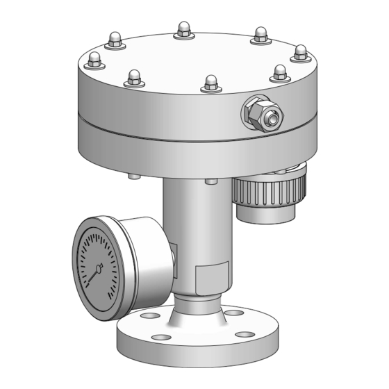
- Page 1 Operating instructions Chlorine gas vacuum regulator C 2560-V Please read this manual before starting up! To be retained for future reference.
-
Page 3: Table Of Contents
12.3 Disposing of an old device..........Product description ............10 13 Spare parts ..............Scope of delivery ............10 13.1 Inlet valve C 2560-V ............Structure of a vacuum dosing system ......10 13.2 Vacuum unit C 2560-V........... Structure of the device ..........10 13.3 Maintenance kits ............ -
Page 4: About These Operating Instructions
1 | About these operating instructions 1 About these operating instructions DANGER This document: • Is part of the product. Imminent danger • Describes the safe and correct use of the product in all operating Non-compliance can result in death or serious injury. phases. -
Page 5: Action Steps
Example: (→ Fig. 5) 1.6 Latest version Please find the latest version of these operating instructions at www.lutz-jesco.com. 1.7 Copyright The content of these operating instructions and the images contained in them are subject to the copyright protection of Lutz-Jesco GmbH. -
Page 6: Safety
2 | Safety 2 Safety WARNING 2.1 Dangers when handling chlorine Increased risk of accidents due to insufficient qualification of The following warnings are intended to help you eliminate the personnel! dangers that can arise while handling the device. Risk prevention Only sufficiently qualified personnel may install, operate and main- measures always apply regardless of any specific action. -
Page 7: Product Safety
2 | Safety 2.3 Product safety • Damage to the product and other damage to property • Environmental damage The device is constructed in accordance with the state of the art and recognised safety regulations. Nevertheless, their use may pose a •... -
Page 8: Personnel Tasks
2 | Safety • Sufficient qualification for the respective activity • Training into the handling of the device • Knowledge of safety equipment and the way this equipment functions • Knowledge of these operating instructions, particularly the safety instructions and sections relevant for the activity •... -
Page 9: Intended Use
• Information on usage and environment is not adhered to. • People operate the product who are not adequately qualified to carry out their respective activities. • No original spare parts or accessories of Lutz-Jesco GmbH are used. • Unauthorised changes are made to the product by the user. -
Page 10: Product Description
4 | Product description 4 Product description 4.3 Structure of the device 4.1 Scope of delivery Carefully check the delivery prior to installation and refer to the deliv- ery note to ensure that the delivery is complete and to check for any transport damage. -
Page 11: Function Description
Chlorine (positive pressure) Fig. 4: Sectional view of the chlorine gas vacuum regulator C 2560-V Chlorine gas flows under pressure out of the chlorine drum into the vacuum regulator. The vacuum regulator consists of an inlet valve (1) and the diaphragm chamber (3). The chlorine gas in the inlet valve is under positive pressure; a vacuum is in the diaphragm chamber. -
Page 12: Rating Plate
Lutz-Jesco GmbH 30900 Wedemark Am Bostelberge 19 C 2560-V Material: PVC/FPM/Monel/Ms58 XX/XXXX P/N: S/N: Made in Germany Fig. 5: Rating plate C 2560-V 1 Product name 2 Materials 3 Serial number 4 Part number 5 Month of manufacture 6 Year of manufacture... -
Page 13: Technical Data
5 | Technical data 5 Technical data Description Value Chlorine gas flow rate up to 60 kg/h Inlet pressure 1.5 – 16 bar Operating vacuum -50 mbar Opening pressure of the safety valve 100 mbar Optional pressure gauge 0 – 16 bar / Ø 63 mm Inlet valve Brass (chemically nickel-plated), Monel, Hastelloy Materials... -
Page 14: Dimensions
Value Ø C 20800100_7 Ø 170 8/12 Ø C 1" NPT Fig. 6: Dimensions (C 2560-V with threaded connection) Ø 170 8/12 Ø C Flange: DN25 / PN40 with groove (EN 1092) Form D Ø 85 Fig. 7: Dimensions (C 2560-V with flange connection) -
Page 15: Installation
Titelbild mit Flansch C 2560-V 20800100_1 tank to the vacuum regulator should not exceed 0.5 bar. Therefore, The device may not be exposed to direct sunlight. -
Page 16: Chlorine Outlet (Vacuum Line)
7 | Installation Fig. 10: Seal in the thread NOTE Fig. 9: Installing the flange connection Leakage due to incorrect installation 1. Place the flat gasket (2) onto the protruding spring of the con- necting flange (1). Assemble the seal in dry condition. To ensure that the connection is correctly aligned, it is necessary un- der certain circumstances to turn the thread anticlockwise. -
Page 17: Safety Valve
7 | Installation 4. Mount the connection on the device. Ensure that the O-ring is in- Length of the vacuum line Mass flow of stalled. chlorine 10 m 20 m 30 m 50 m 100 m 5. Tighten the union nut by hand. 60 kg/hr DN20 DN20... -
Page 18: Completing The Installation
7 | Installation 7.3.4 Completing the installation After completing installation, you must check all connections for leak- tightness. → Inspection of the pressure system [} 19] and Inspection of the vacuum system [} 20] INFORMATION All exposed bright metal surfaces must be painted as the atmosphere in chlorine gas rooms is highly corrosive. -
Page 19: Commissioning
8 | Commissioning 8 Commissioning 8.1.2 Performing a leak test with chlorine DANGER DANGER Danger to life from chlorine poisoning! Chlorine gas can escape due to systems that are leaky or not in- stalled correctly! If you start the leak test with chlorine before the entire system has been installed and the ejectors are ready for operation, chlorine can- Chlorinators constitute an increased safety risk if they have not been not be extracted immediately in the case of a leakage. -
Page 20: Inspection Of The Vacuum System
8 | Commissioning 8.2 Inspection of the vacuum system ü If the system was previously operated with chlorine, the residual chlorine has been extracted with the ejector and the system op- erated for approx. 5 minutes using nitrogen or dry compressed NOTE air. -
Page 21: Operation
9 | Operation 9 Operation DANGER Chlorine gas can escape due to systems that are leaky or not in- stalled correctly! Chlorinators constitute an increased safety risk if they have not been properly installed, if an adequate leak test has not been performed or if the devices are not in good condition. -
Page 22: Maintenance
The numbers in brackets refer to the items in Table 7: Spare parts for After 5 years • Replace the pressure gauge inlet valve C 2560-V [} 27]. Table 5: Maintenance intervals INFORMATION 10.4.1 Dismantling the inlet valve 1. Remove the screws (9) which fasten the flange (6) on the plastic In some cases, regional regulations may require shorter maintenance part of the vacuum regulator. -
Page 23: Clean The Inlet Valve
The numbers in brackets refer to the items in Table 8: Spare parts for 7. Fit the screws (8) with a little fitting grease. vacuum unit C 2560-V [} 28]. 8. Tighten the screws crosswise with approx. 3 Nm. 9. Fit the pressure gauge (10) with approx. 3 layers of PTFE strip. -
Page 24: Checking The Vacuum Unit
10 | Maintenance ü Wearing parts are available. 5. Push the open end under water. 1. Rub the edges of the diaphragm (18.4) with silicone grease 9 The water must not rise in the hose. lightly. O Leakage test concluded. 2. -
Page 25: Troubleshooting
11 | Troubleshooting 11 Troubleshooting See below for information about how to rectify faults on the device or the system. If you cannot eliminate the fault, please consult with the manufacturer on further measures or return the device for repair. Problem Possible Cause Remedy... -
Page 26: Shutdown And Disposal
12 | Shutdown and disposal 12 Shutdown and disposal 12.1 Shutting down the system temporarily 1. Close the chlorine gas container valves. 2. Use the ejector to extract the remaining chlorine. 3. Switch off the ejector. O Chlorine gas system shut down temporarily. 12.2 Shutting down the system for a longer period of time 1. -
Page 27: Spare Parts
13 | Spare parts 13 Spare parts Items included in maintenance kits are labelled "A" or "B" (→ Table 7: Spare parts for inlet valve C 2560-V [} 27] and Table 8: Spare parts for vacuum unit C 2560-V [} 28]). 13.1 Inlet valve C 2560-V Fig. 19: Spare parts for inlet valve C 2560-V... -
Page 28: Vacuum Unit C 2560-V
13 | Spare parts 13.2 Vacuum unit C 2560-V 18.1 18.2 18.3 18.4 18.5 Fig. 20: Spare parts for vacuum unit C 2560-V Item Quantity Description Material Upper section Union nut M16 x 1.5 mm (Ø 12.2 mm) Hose clamp connection 8/12 O-ring Ø 14 mm... -
Page 29: Maintenance Kits
13.3 Maintenance kits Part Content All parts labelled with "A" in Table 7: Spare parts for inlet valve C 2560-V [} 27] and Table 8: Spare parts for vacuum unit C 2560-V [} 28] : • Valve seat Maintenance set for C 2560-V •... -
Page 30: Note On Eu Conformity
This pressure device may not carry a CE marking and an EU declaration of conform- ity will not be issued. Device designation: Vacuum regulator Type: C 2560-V Pressure stage: PN16 Max. temperature: 50 °C Medium: Chlorine, fluid group 1... -
Page 31: Decontamination Declaration
15 | Decontamination declaration 15 Decontamination declaration Due to legal regulations for the protection of our employees and operating facilities, we need the completed and signed declaration of decon- tamination in order to process your return. 1. Copy this page and complete it for each device separately! 2. -
Page 32: Warranty Claim
16 | Warranty claim 16 Warranty claim If the device breaks down within the period of warranty, please return it in a cleaned condition with the fully completed warranty claim. 1. Copy this page and fill in all fields. 2. Pack the device together with the completed warranty claim. 3. - Page 33 Notes...
- Page 36 Lutz-Jesco GmbH Am Bostelberge 19 30900 Wedemark Germany Tel.: (+49 51 30) 58 02-0 E-Mail: info@lutz-jesco.com www.lutz-jesco.com...
Need help?
Do you have a question about the C 2560-V and is the answer not in the manual?
Questions and answers