
Related Manuals for Lutz-Jesco C 2700-V


Summary of Contents for Lutz-Jesco C 2700-V
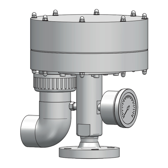
- Page 1 Operating instructions Chlorine gas vacuum regulator C 2700-V Please read this manual before starting up! To be retained for future reference.
-
Page 3: Table Of Contents
Table of contents Table of contents Commissioning............... Inspection of the pressure system ....... About these operating instructions ........ 8.1.1 Performing a leak test with nitrogen ..... Target groups..............8.1.2 Performing a leak test with chlorine....General non-discrimination .......... Inspection of the vacuum system ......... 8.2.1 Performing a leak test of the vacuum system Warnings............... -
Page 4: About These Operating Instructions
1 | About these operating instructions 1 About these operating instructions DANGER This document: • Is part of the product. Imminent danger • Describes the safe and correct use of the product in all operating Non-compliance can result in death or serious injury. phases. -
Page 5: Action Steps
Example: (→ Fig. 5) 1.6 Latest version Please find the latest version of these operating instructions at www.lutz-jesco.com. 1.7 Copyright The content of these operating instructions and the images contained in them are subject to the copyright protection of Lutz-Jesco GmbH. -
Page 6: Safety
2 | Safety 2 Safety WARNING 2.1 Dangers when handling chlorine Increased risk of accidents due to insufficient qualification of The following warnings are intended to help you eliminate the personnel! dangers that can arise while handling the device. Risk prevention Only sufficiently qualified personnel may install, operate and main- measures always apply regardless of any specific action. -
Page 7: Product Safety
2 | Safety 2.3 Product safety • Damage to the product and other damage to property • Environmental damage The device is constructed in accordance with the state of the art and recognised safety regulations. Nevertheless, their use may pose a •... -
Page 8: Personnel Tasks
2 | Safety • Sufficient qualification for the respective activity • Training into the handling of the device • Knowledge of safety equipment and the way this equipment functions • Knowledge of these operating instructions, particularly the safety instructions and sections relevant for the activity •... -
Page 9: Intended Use
• Information on usage and environment is not adhered to. • People operate the product who are not adequately qualified to carry out their respective activities. • No original spare parts or accessories of Lutz-Jesco GmbH are used. • Unauthorised changes are made to the product by the user. -
Page 10: Product Description
4 | Product description 4 Product description 4.3 Structure of the device 4.1 Scope of delivery Carefully check the delivery prior to installation and refer to the deliv- ery note to ensure that the delivery is complete and to check for any transport damage. -
Page 11: Function Description
Chlorine (positive pressure) Fig. 4: Sectional view of the chlorine gas vacuum regulator C 2700-V Chlorine gas flows under pressure out of the chlorine drum into the vacuum regulator. The vacuum regulator consists of an inlet valve (1) and the diaphragm chamber (3). The chlorine gas in the inlet valve is under positive pressure; a vacuum is in the diaphragm chamber. -
Page 12: Rating Plate
The rating plate must be kept legible for the duration of the service life of the product. Lutz-Jesco GmbH 30900 Wedemark Am Bostelberge 19 Chlorine Gas Vacuum Regulator C 2700-V Made in Germany PVC/FPM/Monel/Ms58 XX/XXXX P/N: S/N: Fig. 5: Rating plate C 2700-V... -
Page 13: Technical Data
5 | Technical data 5 Technical data Description Value Throughput up to 200 kg/h Inlet pressure 1.5–16 bar Operating vacuum -50 mbar Opening pressure of the safety valve 500 mbar Pressure gauge (optional) 0–16 bar / Ø 63 mm Inlet valve Brass (chemically nickel-plated), Monel, Hastelloy Materials Vacuum housing... -
Page 14: Dimensions
6 | Dimensions 6 Dimensions All dimensions in millimetres (mm). Ø 224 8/12 1" NPT Fig. 6: Dimensions C 2700-V with threaded connection Ø 224 8/12 Flange DN25/PN40 with groove (form D) compliant Ø 85 with EN 1092 Fig. 7: Dimensions C 2700-V with flange connection... -
Page 15: Installation
7 | Installation 7 Installation 7.3 Installation DANGER 7.3.1 Chlorine input (pressure line) NOTE Increased risk of accidents due to insufficient qualification of personnel! Damage to the system by liquid chlorine Only sufficiently qualified personnel may install, operate and main- tain the device and its accessories. -
Page 16: Chlorine Outlet (Vacuum Line)
7 | Installation ü Bolts, nuts and washers are clean and undamaged. Lubricate ü Required equipment is to hand: grease-dissolving cleaner the sliding faces and thread of bolts, nuts and washers e.g. us- (e.g. isopropyl alcohol) and thread sealant (Omnifit FD20) ing fitting grease or PTFE grease. -
Page 17: Safety Valve
7 | Installation The following nominal widths are recommended for the vacuum line (pressure loss max. 25 bar, calculated at 0.9 bar with 5 x 90° angles): Length of the vacuum line Mass flow of chlorine 10 m 20 m 30 m 50 m 100 m... -
Page 18: Completing The Installation
7 | Installation Fig. 14: Fitting the hose connection 1. Cut the hose (1) a at right angles. 2. Slide the union nut (2) onto the hose. 3. Slide the hose end onto the cone of the hose connection (3). 4. Tighten the union nut by hand. 5. -
Page 19: Installation Examples
7 | Installation 7.4 Installation examples Fig. 15: Installation without a chlorine evaporator A Room for the chlorine supply B Dosing device room 1 Chlorine barrel 2 Chlorine barrel scale 3 Manifold 4 Changeover switch 5 Chlorine gas filter 6 Pressure reducing valve 7 Moisture eliminator with heating collar 8 Vacuum regulator 9 Activated carbon cartridge... -
Page 20: Commissioning
8 | Commissioning 8 Commissioning 8.1.2 Performing a leak test with chlorine DANGER DANGER Danger to life from chlorine poisoning! Chlorine gas can escape due to systems that are leaky or not in- stalled correctly! If you start the leak test with chlorine before the entire system has been installed and the ejectors are ready for operation, chlorine can- Chlorinators constitute an increased safety risk if they have not been not be extracted immediately in the case of a leakage. -
Page 21: Inspection Of The Vacuum System
8 | Commissioning 8.2 Inspection of the vacuum system ü If the system was previously operated with chlorine, the residual chlorine has been extracted with the ejector and the system op- erated for approx. 5 minutes using nitrogen or dry compressed NOTE air. -
Page 22: Operation
9 | Operation 9 Operation DANGER Chlorine gas can escape due to systems that are leaky or not in- stalled correctly! Chlorinators constitute an increased safety risk if they have not been properly installed, if an adequate leak test has not been performed or if the devices are not in good condition. -
Page 23: Maintenance
10 | Maintenance 10 Maintenance 10.3 Preparing the system for maintenance DANGER WARNING Danger to life from chlorine poisoning! Increased risk of accidents due to insufficient qualification of personnel! Do not carry out maintenance or any other work on the chlorinator until the system has been decommissioned and all of the chlorine gas Only sufficiently qualified personnel may install, operate and main- has been removed from the lines. -
Page 24: Dismantling The Inlet Valve
10 | Maintenance 10.4.3 Fitting the inlet valve ü The parts have been dried well after cleaning. ü The parts are in good condition. ü Wearing parts are available. 1. Insert the valve seat (5) through the flange (3) and fit the O-ring (2) into the groove of the valve seat. -
Page 25: Maintenance Of The Vacuum Unit
10 | Maintenance 4. If a leakage develops on the valve output, remove the valve from 2. Perform a visual inspection of the parts that are not included in the water, open the valve by exerting strong pressure on the the maintenance set and replace any damaged parts. -
Page 26: Completing The Maintenance
10 | Maintenance 10.6 Completing the maintenance 1. Make a note of the date and scope of the maintenance per- formed. 2. Attach a sticker displaying the maintenance date to the device. 3. Fit the vacuum regulator in the system. 4. -
Page 27: Troubleshooting
11 | Troubleshooting 11 Troubleshooting See below for information about how to rectify faults on the device or the system. If you cannot eliminate the fault, please consult with the manufacturer on further measures or return the device for repair. Problem Possible Cause Remedy... -
Page 28: Shutdown And Disposal
12 | Shutdown and disposal 12 Shutdown and disposal 12.1 Shutting down the system temporarily 1. Close the chlorine gas container valves. 2. Use the ejector to extract the remaining chlorine. 3. Switch off the ejector. O Chlorine gas system shut down temporarily. 12.2 Shutting down the system for a longer period of time 1. -
Page 29: Spare Parts
13 | Spare parts 13 Spare parts Fig. 23: Spare parts of the chlorine gas vacuum regulator C 2700-V... -
Page 30: Complete Assemblies
13 | Spare parts 13.1 Spare parts 13.2 Complete assemblies Item Quantity Description Info Item Description Housing, bottom part 3–10 Diaphragm disc Front casing Inlet valve without pressure gauge, connection 1" NPT male Diaphragm disc Inlet valve with pressure gauge, connection 1" NPT male Ring diaphragm FPM, Ø 200/122 mm Inlet valve without pressure gauge, connection with... -
Page 31: Note On Eu Conformity
This pressure device may not carry a CE marking and an EU declaration of conform- ity will not be issued. Device designation: Vacuum regulator Type: C 2700-V Pressure stage: PN16 Max. temperature: 50 °C Medium: Chlorine, fluid group 1... -
Page 32: Decontamination Declaration
15 | Decontamination declaration 15 Decontamination declaration Due to legal regulations for the protection of our employees and operating facilities, we need the completed and signed declaration of decon- tamination in order to process your return. 1. Copy this page and complete it for each device separately! 2. -
Page 33: Warranty Claim
16 | Warranty claim 16 Warranty claim If the device breaks down within the period of warranty, please return it in a cleaned condition with the fully completed warranty claim. 1. Copy this page and fill in all fields. 2. Pack the device together with the completed warranty claim. 3. - Page 34 Notes...
- Page 36 Lutz-Jesco GmbH Am Bostelberge 19 30900 Wedemark Germany Tel.: (+49 51 30) 58 02-0 E-Mail: info@lutz-jesco.com www.lutz-jesco.com...
Need help?
Do you have a question about the C 2700-V and is the answer not in the manual?
Questions and answers