Table of Contents
Advertisement
Quick Links
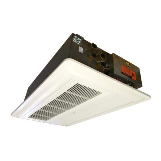
1-WAY CEILING CASSETTE
FAN COIL UNIT
_______________________________________________________________________
Operation and Installation Manual
MH1WC4W
One way ceiling cassette fan coil unit
Please read this manual before using the fan coil unit.
Installation and service must be carried out by trained and qualified technicians only.
Model series covered in this manual are for both 208V and 230V.
Rev. 1.1
Advertisement
Table of Contents

Subscribe to Our Youtube Channel
Related Manuals for Multiaqua MH1WC4W


Summary of Contents for Multiaqua MH1WC4W
- Page 1 1-WAY CEILING CASSETTE FAN COIL UNIT _______________________________________________________________________ Operation and Installation Manual MH1WC4W One way ceiling cassette fan coil unit Please read this manual before using the fan coil unit. Installation and service must be carried out by trained and qualified technicians only.
- Page 2 GENERAL Read the entire contents of this manual before beginning installation. Multiaqua assumes no responsi- bility for equipment installed contradictory to any code requirement or installation instructions. Careful attention has been given to the preparation of this IOM (Installation, Operation Manual) and the content has been carefully compiled for your convenience.
-
Page 3: Table Of Contents
Fan coil unit -MH1WC4W Series Table of Contents INSTALLATION Section 1. Inspection of Packaging Section 2. Safety Precautions Section 3. Operational Limits Section 4. Selection of Installation Location Section 5. Installation of the unit DIMENSIONIAL DRAWINGS EXPLODED VIEWS WIRING DIAGRAM... -
Page 4: Section 1. Inspection Of Packaging
Fan coil unit -MH1WC4W Series PREPARATION FOR INSTALLATION Section 1) P ACKAGE NSPECTION 1. It is advisable to place the unit close to the installation site without removing it from the package. Do not put heavy tools or weights on the package. -
Page 5: Section 4. Selection Of Installation Location
Fan coil unit -MH1WC4W Series Section 4) SELECTION OF INSTALLATION LOCATION 1. Do not install the unit in rooms where any hazards are present including, but not limited to: flammable gas, or hazardous atmosphere exists , alkaline or acid substances. Aluminum/copper coils and/or internal plastic components can be damaged beyond repair. -
Page 6: Section 5. Installation Of The Unit
Fan coil unit -MH1WC4W Series Section 5) INSTALLATION OF THE UNIT 1. Mark position of suspension rods, water pipes, condensate drain, power supply cables, etc. Supporting rods can be fixed, depending on the type of ceiling, as shown in Figure 3. - Page 7 Fan coil unit -MH1WC4W Series Section 5) INSTALLATION OF THE UNIT (Continued) 5. Ensure the unit is level, otherwise condensate water cannot drain properly. 6. Using a level and/or measuring tape, ad- just the height of the bottom of the unit to be level or slightly higher (not more than 1/16”) than the lower part of the...
- Page 8 11. Reinstall cover assembly with the four (4) shoulder screws removed earlier. DO NOT OVER TIGHTEN. 12. Unit is now ready for contractor start-up procedures and recording of benchmark data according to all local and national requirements. Fresh Air Connection Location Typical Piping and Electrical Locations on the MH1WC4W...
-
Page 9: Dimensionial Drawings
Fan coil unit -MH1WC4W Series MH1WC4W Side View (mm) MH1WC4W Top View (mm) - Page 10 Fan coil unit -MH1WC4W Series MH1WC4W Piping Detail (mm)
-
Page 11: Exploded Views
Fan coil unit -MH1WC4W Series MH1WC4W Exploded View... -
Page 12: Wiring Diagram
Fan coil unit -MH1WC4W Series MH1WC4W-XX-1-B Wiring Diagram for PCB Control... - Page 14 Multiaqua Inc. 306 Hagood Street Easley, SC 29640 864-850-8990 IOM MH1WC4W Series 08032016—EN ver. 01/Rev 1.1...
Need help?
Do you have a question about the MH1WC4W and is the answer not in the manual?
Questions and answers