Advertisement
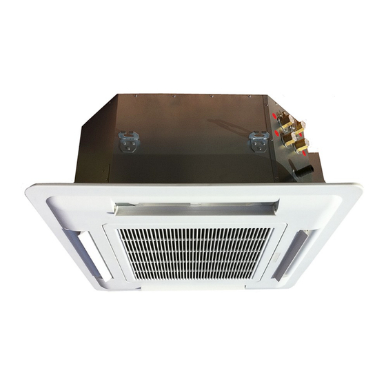
CEILING CASSETTE
FAN COIL UNIT
________________________________________________________________________________
Operation and Installation Manual
MHCFC4W-04, 08, 12, 16
Four way ceiling cassette fan coil unit
Please read this manual before using the fan coil unit.
Installation and service must be carried out by trained and qualified technicians only.
These specifications are subject to change without notice.
Check www.multiaqua.com for latest published information.
Rev. 1.1
Advertisement

Subscribe to Our Youtube Channel
Related Manuals for Multiaqua MHCFC4W-12


Summary of Contents for Multiaqua MHCFC4W-12
- Page 1 Four way ceiling cassette fan coil unit Please read this manual before using the fan coil unit. Installation and service must be carried out by trained and qualified technicians only. These specifications are subject to change without notice. Check www.multiaqua.com for latest published information. Rev. 1.1...
- Page 2 GENERAL Read the entire contents of this manual before beginning installation. Multiaqua assumes no responsibil- ity for equipment installed contradictory to any code requirement or installation instructions. Careful attention has been given to the preparation of this IOM (Installation and Operation Manual) and the content has been carefully compiled for your convenience.
-
Page 3: Table Of Contents
Section 2. Safety Precautions Section 3. Operational Limits Section 4. Selection of Installation Location Section 5. Installation of the unit DIMENSIONIAL DRAWINGS 9-16 EXPLODED VIEWS 17,18 These specifications are subject to change without notice. Check www.multiaqua.com for latest published information. -
Page 4: Section 1. Inspection Of Packaging
Power supply: Please refer to the label attached to the unit for correct power supply. Minimum entering water temperature: 35.6°F Maximum entering water temperature: 160 °F Maximum water system pressure shall not exceed: 200 psi These specifications are subject to change without notice. Check www.multiaqua.com for latest published information. -
Page 5: Section 4. Selection Of Installation Location
The dimensions shown in Figure 2 are suggestions. Your application may require more space to access controls, control valves, pumps, etc. Figure 2 These specifications are subject to change without notice. Check www.multiaqua.com for latest published information. -
Page 6: Section 5. Installation Of The Unit
C. After the unit is secured to the lift, carefully lift the unit to ceiling height. 4. Now that the unit is at ceiling height, attach threaded rods to mount- ing brackets of the units. See Figure 4. These specifications are subject to change without notice. Check www.multiaqua.com for latest published information. - Page 7 11. Reinstall cover assembly with the four (4) shoulder screws removed earlier. DO NOT OVER TIGHTEN. 12. Unit is now ready for contractor start-up procedures and recording of benchmark data according to all local and national requirements. These specifications are subject to change without notice. Check www.multiaqua.com for latest published information.
- Page 8 Model 04 3.50L x 2.50H Model 08 5.25L x 2.50H Model 12 6.50L x 2.50H Model 16 7.00L x 3.75H Fresh Air Connections Typical Locations on MHCFC4W-08,12,16 These specifications are subject to change without notice. Check www.multiaqua.com for latest published information.
-
Page 9: Dimensionial Drawings
MHCFC4W-04 15.6 Side View All dimensions are in inches 24.2 MHCFC4W-04 Top View 22.8 16.7 26.8 These specifications are subject to change without notice. Check www.multiaqua.com for latest published information. - Page 10 Barbed Fitting Condensate Connection 10.375 Chilled Water Inlet 10.625 Hot Water inlet 13.0 Chilled Water Outlet with vent 13.5 Hot Water with vent DRAWING NOT TO SCALE These specifications are subject to change without notice. Check www.multiaqua.com for latest published information.
- Page 11 MHCFC4W-08 MHCFC4W-08 15.6 Side View All dimensions are in inches 28.0 13.3 MHCFC4W-08 Top View 32.7 29.01 These specifications are subject to change without notice. Check www.multiaqua.com for latest published information.
- Page 12 Condensate Drain Connection 9.312 Hot Water Inlet 9.75 Chilled Water Inlet 12.25 Hot Water Outlet with vent 12.875 Chilled Water Outlet with vent DRAWING NOT TO SCALE These specifications are subject to change without notice. Check www.multiaqua.com for latest published information.
- Page 13 MHCFC4W-12 MHCFC4W-12 16.9 Side View All dimensions are in inches 38.6 32.8 16.3 Top View MHCFC4W-12 34.0 These specifications are subject to change without notice. Check www.multiaqua.com for latest published information.
- Page 14 Condensate Drain Connection 9.312 Hot Water Inlet 9.75 Chilled Water Inlet 12.25 Hot Water Outlet with vent 12.875 Chilled Water Outlet with vent DRAWING NOT TO SCALE These specifications are subject to change without notice. Check www.multiaqua.com for latest published information.
- Page 15 MHCFC4W-16 MHCFC4W-16 16.9 Side View All dimensions are in inches 44. 75 Top View 38. 25 19.2 5 MHCFC4W-16 39. 5 These specifications are subject to change without notice. Check www.multiaqua.com for latest published information.
- Page 16 Condensate Drain Connection 9.875 Hot Water Inlet 10.375 Chilled Water Inlet 12.875 Hot Water Outlet with vent 13.375 Chilled Water Outlet with vent DRAWING NOT TO SCALE These specifications are subject to change without notice. Check www.multiaqua.com for latest published information.
-
Page 17: Exploded Views
4. Fan Motor 5. Fan Blade 6. Coil Assembly 7. Condensate Pan Assembly 8. Fan Venturi 9. Fan Blade Guard 10. Filter Element 11. Cover Assembly These specifications are subject to change without notice. Check www.multiaqua.com for latest published information. -
Page 18: Exploded Views
4. Fan Motor 5. Fan Blade 6. Coil Assembly 7. Condensate Pan Assembly 8. Fan Venturi 9. Fan Blade Guard 10. Filter Element 11. Cover Assembly These specifications are subject to change without notice. Check www.multiaqua.com for latest published information. - Page 19 Fan coil unit - MHCFC4W Series These specifications are subject to change without notice. Check www.multiaqua.com for latest published information.
- Page 20 Fan coil unit - MHCFC4W Series These specifications are subject to change without notice. Check www.multiaqua.com for latest published information.
- Page 21 IOM MHCFC4W Series 120823 ver. 1H These specifications are subject to change without notice. Check www.multiaqua.com for latest published information.
Need help?
Do you have a question about the MHCFC4W-12 and is the answer not in the manual?
Questions and answers
does the MHCFC4W – 04 have A built-in condensate pump