Table of Contents
Advertisement
Quick Links
INSTALLATION &
OWNER'S MANUAL
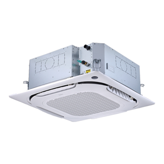
Compact Four-way Cassette
MI2-22DQ4CDN18(At) (KCIF-22 DR5.0H)
MI2-28DQ4CDN18(At) (KCIF-28 DR5.0H)
MI2-36DQ4CDN18(At) (KCIF-36 DR5.0H)
MI2-56DQ4CDN18(At) (KCIF-56 DR5.0H)
Read this manual carefully before using the product, and keep it handy for future reference.
The product picture on the cover page is for reference only.
Advertisement
Table of Contents

Related Manuals for Frigicoll MI2-22DQ4CDN18(At)


Summary of Contents for Frigicoll MI2-22DQ4CDN18(At)
- Page 1 INSTALLATION & OWNER’S MANUAL Compact Four-way Cassette MI2-22DQ4CDN18(At) (KCIF-22 DR5.0H) MI2-28DQ4CDN18(At) (KCIF-28 DR5.0H) MI2-36DQ4CDN18(At) (KCIF-36 DR5.0H) MI2-56DQ4CDN18(At) (KCIF-56 DR5.0H) Read this manual carefully before using the product, and keep it handy for future reference. The product picture on the cover page is for reference only.
- Page 2 Preface Dear users, Thank you for purchasing and using our product. Please read this manual carefully before you install, use, maintain or troubleshoot this product so that you can familiarize yourself with the product and use it correctly. For ODUs or other IDUs, please refer to the applicable installation & owner’s manuals provided with them.
-
Page 3: Table Of Contents
Contents Safety Warning Warning Signs / 1 Safety Precautions / 2 Electric Safety Requirements / 3 Appendix / 3 Operation Operation Precautions / 7 Optimum Operation / 8 Symptoms That Are Not Faults / 9 Display Panel / 11 Installation Installation Materials / 20 Installation Precautions / 12 IDU Installation / 24... -
Page 4: Warning Signs
Please thoroughly read and ensure that you fully understand the safety precautions (including the signs and symbols) in this manual, Safety Warning and follow relevant instructions during use to prevent damage to health or property. Explanation of symbols displayed on the unit This symbol shows that this appliance used a flammable refrigerant. -
Page 5: Safety Precautions
Warning contents Ensure Proper Grounding Professional Only Prohibition signs No Flammable Materials No Strong Current No Open Fire No Acid or Alkali Materials Safety Precautions Danger During thunderstorms, disconnect the main power switch. Otherwise, lightning may damage the unit. In the event of refrigerant leakage, smoking and open flames are prohibited. Disconnect the main power switch immediately, open windows to allow ventilation, keep away from the leakage point, and contact your local dealer or technical support to request a professional repair. -
Page 6: Electric Safety Requirements
Electric Safety Requirements Warning The air conditioner shall be installed according to the local wiring specifications. Wiring work must be completed by qualified electricians. All wiring work must comply with electrical safety specifications. The air conditioner must be well grounded. Specifically, the main switch of the air conditioner must have a reliable grounding cable. - Page 7 non-sparking, adequately sealed or intrinsically safe. If any hot work is to be conducted on the refrigeration equipment or any associated parts, appropriate fire extinguishing equipment shall be available to hand. Have a dry powder or CO2 fire extinguisher adjacent to the charging area.
- Page 8 When breaking into the refrigerant circuit to make repairs – or for any other purpose – conventional procedures shall be used. However, it is important that best practice is followed. Since flammability is a consideration. The following procedure shall be adhered to: •...
- Page 9 The recovered refrigerant shall be returned to the refrigerant supplier in the correct recovery cylinder, and the relevant Waste Transfer Note arranged. Do not mix refrigerants in recovery units and especially not in cylinders. If compressors or compressor oils are to be removed, ensure that they have been evacuated to an acceptable level to make certain that flammable refrigerant does not remain within the lubricant.
-
Page 10: Operation
Operation Operation Precautions Warning If the unit will be not used for a long time, disconnect the main power switch. Otherwise, an accident may occur. The installation height of the air conditioner shall be at least 2.5m above the ground to avoid the following risks: 1. -
Page 11: Optimum Operation
Disposal: Do not dispose of this product as unsorted municipal waste. Collection of such waste separately for special treatment is necessary. Do not dispose of electrical appliances as unsorted municipal waste, use separate collection facilities. Contact your local government for information regarding the collection systems available. If electrical appliances are disposed of in landfills or dumps, hazardous substances can leak into the groundwater and get into the food chain, damaging your health and well-being. -
Page 12: Symptoms That Are Not Faults
Operating Range To maintain good performance, operate the air conditioner under the following temperature conditions: Indoor temperature 16~32°C ≤80% Cooling Indoor humidity (When the humidity exceeds 80%, long-time operation of the IDU may cause dew condensation on the surface of the IDU or generate mist-like cold air from the air outlet.) Heating Indoor temperature 15~30°C... - Page 13 Normal Phenomena that Are Not Air Conditioner Faults The following phenomena are normal during operation of the air conditioner. They can be solved according to the instructions below or do not need to be solved. The IDU emits white mist ①...
-
Page 14: Display Panel
Display Panel Display functions: In Standby mode, the main interface displays “---”. ① When starting up in Cooling or Heating mode, the main interface displays the set temperature. In Fan mode, the main ② interface displays the indoor temperature. In Dry mode, the main interface displays the set temperature, and when the humidity is set, the set humidity value is displayed on the wired controller. -
Page 15: Installation
Installation Carefully read this manual before installing the IDU. Installation Precautions Qualification and Safety Regulation Requirements Warning Please carry out the installation according to local standards. Ask your local dealer or professionals to install the product. This unit must be installed by professional technicians with relevant specialized knowledge. Users MAY NOT install the unit themselves;... - Page 16 Before and after installation, exposing the unit to water or moisture will cause electrical parts short circuiting. Do not store the unit in a humid basement or expose it to rain or water. Make sure the installation base and lifting are robust and reliable; Insecure installation of the base may cause the air conditioner to fall, leading to an accident.
- Page 17 Precautions for Carrying and Lifting the Air Conditioner Before carrying the air conditioner, determine the route that will be used to move it to the installation site. Do not unseal the air conditioner until it is moved to the installation site. When unpacking and moving the air conditioner, you must hold the hanger seat and not apply force to other parts, especially the refrigerant piping, drainage pipe and plastic accessories, so as to avoid damaging the air conditioner and causing personal injury.
- Page 18 The nearer the drainage pipe and copper pipe are to the ODU, the lower the pipe cost is. Prevent the air conditioner from blowing directly at the human body. The closer the wiring is to the power cabinet, the lower the wiring cost is. Keep the air-conditioning return air away from direct exposure to the sun in the room.
- Page 19 Ceiling Air outlet Air outlet Panel Air inlet 590x590 (ceiling opening dimension) Floor Installation...
- Page 20 Recommended Installation Sites Crowded places such as living rooms and offices The air outlet must not face the areas where people frequently spend time, such as sofas and coffee tables. Instead, let the airflow exit from the side for enhanced comfort. Air outlets at corners can be blocked with optional accessories (which can be found in the packaging material) Blockage...
- Page 21 Parts Part Description Panel (optional) Air outlet Expanded air inlet/outlet Fresh air inlet Liquid pipe Gas pipe Drainage pipe *Connection wire 10 Wired controller (optional) 11 Remote controller (optional) 12 Electric control box 13 Access hole 14 *Power cable and ground wire 15 *Communication line 16 North American inlet hole (two) * To be purchased separately on site.
- Page 22 Product Dimensions (Unit: mm) Φ22.2 Φ22.2 Φ125 6-M4 Φ170 Φ170 6-M4 6-M4 620 (with panel) Φ23 (internal diameter) Drainage pipe Φ25 (OD) Model (kW) A: Connect to refrigerant piping (liquid side) B: Connect to refrigerant piping (gas side) kW≤5.6 Φ6.35 Φ12.7 5.6<kW≤6.3 Φ9.52...
-
Page 23: Installation Materials
Installation Materials Accessories List of accessories Installation & Owner’s Manual X 1 Brass nut X 2 Cable tie X 4 Thermal insulation pipe X 2 IDU Installation Instructions (Make For use in the installation of To tighten the drainage hose tightly Used for insulation and anti- sure to hand it over to the user) connecting pipe (the quantity is... - Page 24 Locally Purchased Accessories List of accessories Copper pipe PVC water discharge pipe Thermal insulation pipe Expansion screw (M10)X4 Lifting screw (M10)X4 Used to connect the indoor Used to drain the Used to prevent pipe Used to install the IDU. Used to install the IDU. refrigerant piping.
-
Page 25: Preparations Before Installation
Preparations Before Installation Unpacking Check ① Before installation, check whether the packing materials are in good condition, The red whether the accessories that come with the product are complete, whether the dot bulges Sealing air conditioner is intact, and whether the surfaces of the heat exchanger and other parts are worn. - Page 26 Determine the positions of the ceiling opening, the unit and the lifting screws Cut a hole with a size of 590mm x 590mm according to the (Unit: mm) outline of the mounting cardboard. 4-Φ12 Shape cutting of the mounting cardboard 378±1 530±1 (suspender distance) Φ20 (middle opening Φ12)
-
Page 27: Idu Installation
If necessary, cut out the required openings for installation on the ceiling (where there is an existing ceiling). (Unit: mm) For the dimensions of ceiling openings, refer to the following figure. Connect to Suspender drainage pipe installation Connect to refrigerant piping (liquid side) Hexagon nut Connect to refrigerant piping... - Page 28 Refer to the following table on installation using the lifting bolts. Sites with concrete slabs With steel frame Use embedded bolts and pull bolts Directly set and use an angle iron for support. Lifting bolts Angle iron for Lifting bolts support IDU Installation Caution...
- Page 29 Confirm the installation hook position according to the installation hook holes located in the four corners of the mounting cardboard. a. Drill four holes with a diameter of Φ12mm and a depth of 50–55mm on the roof according to the specified position, and then embed expansion hooks.
- Page 30 Fresh air flange Flange connecting screws (6 pcs) Warning When connecting the fresh air unit, insulate the fresh air pipe with foam insulation materials that are at least 10mm thick. The temperature difference between the fresh air provided by the fresh air unit to the IDU and the indoor temperature shall not exceed 5°C, otherwise there is a risk of condensation in the return air area of the air conditioner.
- Page 31 Main body of air conditioner M6×20 screw Mounting (Panel) cardboard Carry out installation as described above (Point 3 of Existing Ceiling installation). Remove the mounting cardboard. Note Make sure the IDU unit is level: Use a spirit level or a transparent rubber hose filled with water to correct the level of the IDU, otherwise water leakage may occur.
- Page 32 Install the panel Install the panel on the IDU using bolts (M5×20) and washers. Drain side Bolts and washers Make sure the two hooks are well secured. Panel hook (two) Tighten the screws under the panel hooks until the thickness of the sealing sponges 1 and 2 between the IDU and the panel outlet is reduced to about 4-6mm.
- Page 33 Caution Improper screw tightening may cause the failure shown in the figure below. After tightening the screws, if there is still a gap between the ceiling and the panel, the height of the IDU must be readjusted. If the lift level of the IDU and the drainage pipes are not affected, you can remove the panel and readjust the height of the IDU.
-
Page 34: Refrigerant Connecting Piping Installation
Refrigerant Connecting Piping Installation Length and Level Difference Requirements for the Pipe Connections of IDU and ODU Different ODUs have different requirements for length and level differences for the piping. Refer to the Installation & Owner’s Manual attached with the ODU. Warning During the installation of the connecting pipes, do not allow air, dust, and other debris to penetrate the piping system, and make sure the interior of the pipes is dry. - Page 35 Pipe Connection Steps Measure the required length of the connecting pipe. Make the connecting pipe using the following method (see “Pipe Connection” for details). Connect the IDU first, then connect the ODU. Before tightening the flare nut, apply refrigeration oil on the inner and outer surface of the pipe flare (you must use refrigeration oil compatible with the refrigerant for this model), and turn it 3 or 4 turns by hand to tighten it.
- Page 36 Nitrogen displacement When brazing pipes, fill the pipes with nitrogen. First evenly heat the inner pipes, then the outer pipes, and fill the joints with welding material. Warning When it is necessary to fill the piping with nitrogen during welding, the pressure must be kept at 0.02MPa using a pressure relief valve.
- Page 37 The protective nut is a one-time part, it can not be reused. In case it is removed, it should be replaced with a new one.(For IEC 60335-2-40: 2018 only) Handle Yoke Cone Copper pipe Clamp handle Red arrow mark Protective nut Indoor unit tubing Flare nut Pipings...
- Page 38 Vacuum Pumping Check valve Connect the refrigerant piping to the gas and liquid pipes of the ODU, and use a vacuum pump to evacuate the gas and liquid pipes of the ODU at the same time. High pressure gauge Do not use the refrigerant enclosed in Pump valve the ODU for vacuuming.
-
Page 39: Drainage Pipe Installation
Drainage Pipe Installation Caution Before installation of the condensate pipeline, determine its direction and elevation to avoid intersection with other pipelines to ensure that the slope is smooth and straight. The highest point of the drainage pipe should be equipped with a discharge port to ensure the smooth discharge of condensate water, and the discharge port must face downwards to prevent dirt from entering the pipe. - Page 40 The drainage pipes of the unit (especially the indoor part) must be evenly wrapped with thermal insulation pipes and fastened with cable ties to prevent air from entering and producing condensate water. Cable tie Drainage pipe Thermal insulation pipe To prevent water from flowing back into the air conditioner when it stops running, the drainage pipe should be inclined downward to the outdoor side (drainage side), with a downward slope of 1/100 or more.
- Page 41 The end of the drainage pipe must be more than 50mm above the ground or from the base of the water discharge slot. In addition, do not submerge it in water. To discharge the condensed water directly into a ditch, the water discharge pipe must bend upwards to form a U-shaped water plug to stop odors from entering the room via the water discharge pipe.
- Page 42 Water Discharge Test Before the test, make sure that the water discharge pipeline is smooth, and check that each connection is properly sealed. Conduct the water discharge test in a new room before the ceiling is plastered. ■ The drainage pipe can be made of PVC pipe (outer diameter: 25mm). Based on the actual installation circumstances, users can purchase pipes of appropriate lengths from a sales agent or the local after-sales service center, or purchase them directly from the market.
-
Page 43: Electrical Connection
Electrical Connection Danger The power supply must be cut off before any electrical work is carried out. Do not conduct electrical work when the power is on; otherwise, it may cause serious personal injury. The air conditioning unit must be grounded reliably and must meet the requirements of the local country/region. If the grounding is not reliable, serious personal injury due to electric leakage may occur. - Page 44 Electrical Characteristics Electric specifications of the IDU Unit power IFM power Frequency Voltage (kW) input (Hz) 0.46 0.37 0.54 0.43 220~240 0.54 0.43 0.65 0.52 Notes: MCA: Min. Circuit Amps. (A), which is used to select the minimum circuit size to ensure safe operation over a long period of time.
- Page 45 Caution All weak point connection points meet SELV, such as X1, X2, P, Q, E, M1, M2, CN18, CN55 etc. Wiring Open the IDU’s electric control box cover. ① Remove the two screws at the positions shown in the figure; ②...
- Page 46 Power cable connection ① Connection between the power cable and power Main control board supply terminal The power supply terminal of the IDU is fixed to the main control board, and the power cable is connected to the power supply terminal labeled “CN1”...
- Page 47 ② Power cable system connection Power cable system connection depends on the forms of communication between the IDU and ODU. For the HyperLink communication form with an independent power supply, IDUs are allowed to have an independent power supply. For other communication forms, IDUs should be provided with uniform power supply.
- Page 48 IDUs are provided with uniform power supply*, which are wired as follows: 1. HyperLink communication with the uniform power supply: Power supply for IDU L1+La+Ln ≤ 2000m Wire diameter: 0.75mm Communication wire ×× Circuit breaker Power cable Distribution box Distribution box Master ODU IDU 1# IDU (n-1)#...
- Page 49 Caution When the IDUs are provided with a uniform power supply, if the IDUs in the same refrigerant system are V8/S8 IDUs, then IDUs and ODU can communicate either via HyperLink with a uniform power supply, or via P/Q communication. If some of the IDUs in the same refrigerant system are non-V8/S8 series, then IDUs and ODU can only communicate via P/Q or P/Q/E communication.
- Page 50 Communication line connection ① Selection of communication method for IDUs Equipped with independently developed HyperLink (M1M2) communication, V8/S8 series IDUs also preserve the previous RS-485 (PQE) communication method. They are compatible with non-V8/S8 IDUs. Pay attention to the type of IDU you have purchased before connecting communication lines.
- Page 51 Caution Please select the communication line according to the requirements in the above reference table. Use shielded cables for communication when strong magnetism or interference is present. On-site wiring must comply with the relevant regulations of the local country/region and must be completed by professionals.
- Page 52 ③ IDU and ODU communication HyperLink communication (with independent power supply) Single unit: HyperLink communication is a new type of IDU and ODU communication technology. When the IDUs are provided with independent power supplies, use 2×1.5mm communication cables. M1 and M2 ports are located at terminal block “CN10”...
- Page 53 Caution If the total distance is ≤ 200m and the total number of IDUs is ≤ 10 sets, the valve is powered and controlled by the master ODU. If the total distance is longer than 200m or the total number of IDUs is more than 10 sets, a repeater is required to increase the bus voltage.
- Page 54 System: The HyperLink communication line with a uniform power supply between IDU and ODU can reach a length of up to 2000 meters, supporting any topology connection. The following figure shows a serial connection: Power supply for IDU Communication wire Circuit breaker Power cable Distribution box...
- Page 55 System: The maximum total length of the P/Q communication cable of the IDU and ODU can be up to 1200m, and can be connected in serial, as shown in the figure below: Power supply for IDU ×× Communication wire Circuit breaker Power cable Distribution box Distribution box...
- Page 56 Caution When P/Q or P/Q/E communication is used, the IDUs need to be powered uniformly. Either P/Q, P/Q/E communication or HyperLink communication can be selected. If it is required for IDUs to have independent power supplies, then HyperLink communication must be selected. Use only shielded cables for P/Q or P/Q/E communication.
- Page 57 ⑤ D1D2 communication line connection (limited to ODU and system configuration) Achieving one-to-multiple and two-to-multiple functions of the IDU wired controller through D1D2 communication (a maximum of 16 sets) D1D2 communication is 485 communication. The one-to-more and two-to-more functions of the IDU wired controller can be achieved through D1D2 communication, as shown in the figure below: IDU 2# IDU 16#...
- Page 58 External board connection (limited to ODU and system configuration) The external board is a connection module outside the main control board, including a display panel, a function module adapter board, and 1# and 2# Expansion boards . ① Display panel connection The display panel is connected to the main control board through a 4-core cable, and is connected to the “CN30”...
- Page 59 Reclose the electric control box cover Straighten out the connecting wires and lay them flat, and close the electric control box cover again. Caution Do not cover the electric control box during power-on. When covering the electric control box, arrange the cables carefully and do not clip the connecting wires on the electric control box cover.
-
Page 60: Application Control
Application Control Error Codes and Definitions In the following circumstances (warning failures excluded), please stop the air conditioner immediately, cut off the power switch and contact the local air conditioner customer service center. The error code is displayed on the display panel and the wired controller display. - Page 61 Error Error code Digital display Abnormal communication between the IDU and ODU Abnormal communication between the IDU main control board and fan drive board Abnormal communication between the IDU and wired controller Abnormal communication between the IDU and Wi-Fi Kit Abnormal communication between the IDU main control board and display board Abnormal communication between the AHU Kit slave unit and master unit Number of AHU Kits is not the same as the set number...
- Page 62 Error Error code Digital display The built-in room temperature sensor of the wired controller short-circuits or cuts off The wireless temperature sensor short-circuits or cuts off The external room temperature sensor short-circuits or cuts off Tcp (pre-cooled fresh air temperature sensor) short-circuits or cuts off Tph (pre-heated fresh air temperature sensor) short-circuits or cuts off TA (outlet air temperature sensor) short-circuits or cuts off Outlet air humidity sensor fault...
- Page 63 Error Error code Digital display Low bus voltage fault High bus voltage fault Phase current sample bias error Motor and IDU are unmatched IPM and IDU are unmatched Motor startup failure Motor blocking protection Speed control mode setting error Phase lack protection of motor Operating Status Codes and Definitions (Non-Error) Definition Code...
- Page 64 Spot Check Description Use the bi-directional communication wired controller (for example, WDC3-86S) to activate the spot check function in the following steps: ① On the main page, hold " " and "▲" for 2s to enter the Check No. query page. The ODU displays u00-u03, the IDU displays n00-n63 (the last two digits show the IDU address), and Spot check the wired controller displays CC.
- Page 65 ESP Setting Use the bi-directional communication wired controller (for example, WDC3-86S) to set the unit external static pressure, which can be divided into the following two situations: Constant speed mode The bi-directional communication wired controller must be used to set the unit external static pressure parameters to overcome the air outlet resistance.
-
Page 66: Test Run
Test Run Before the Test Run, Make Sure That • IDUs and the ODU are properly installed. • The piping is correct, and the refrigerant piping system has been checked for leakage. • Piping length and the amount of refrigerant charged have been recorded. •... - Page 67 Inspection After Installation To ensure a comfortable indoor environment, please run down through the list to check whether the installation of the air conditioner meets the requirements. Insert a “×” for Fail and a “√” for Pass. Check Result Check Item Check Criteria (Pass/Fail) The air conditioner does not fall or...
-
Page 68: Cleaning, Maintenance And After-Sales Service
Cleaning, Maintenance and After-Sales Service Safety Warning Warning For safety reasons, always turn off the air conditioner and turn off the power before cleaning the air conditioner. Do not disassemble or repair the air conditioner by yourself; otherwise, it may cause fire or other hazards. Only professional service personnel can carry out the maintenance. - Page 69 Procedure diagram Remove the air inlet grille. Press the grille clamp with two fingers at the same time,and pull out the air inlet grille in a downward direction. Flip the grille clamp to the center. Remove the filter. Note Only professionals can change and disassemble the filter. Any improper operations may cause electric shock or injuries due to touching rotating parts.
- Page 70 Cleaning Air Outlets and Exterior Panels Wipe the air outlet and panel with a dry cloth. If a stain is hard to remove, clean it with clean water or neutral detergent. Caution Do not use gasoline, benzene, volatile agents, decontamination powder or liquid insecticides. Otherwise, the air outlet or panel may become discolored or deformed.
-
Page 71: Maintenance Of Conventional Parts
Maintenance of Conventional Parts Maintenance of the Electric Control Board Open the electric control box cover. Remove the main control board. Remove the two screws at the positions shown in the Unplug the terminals on the main control board and figure, and pull out the bottom end of the electric control remove the screws at the positions shown in the figure. - Page 72 Open the electric control box cover and untie the cable Remove the sealing plate assembly. tie. Remove the screws at the position shown in the figure, remove the sealing plate assembly, and loosen the wire binding sponge at the outlet. Screw (two) Electric control box cover Screw (three)
- Page 73 Evaporator Maintenance Unplug the corresponding terminals on the main control board. Follow the steps above to remove the panel and drain pan. Remove the sealing plate assembly. After removing one fixing screw, remove the evaporator fixing board. Remove the screws fixing the evaporator and the pump bracket in place, and remove the evaporator.
- Page 74 Maintenance of Water Pump Unplug the water pump terminal on the main control board. Follow the steps above to remove the panel and drain pan. Unplug the drainage pipe. After removing the two fixing screws, the pump can be taken out for replacement or maintenance. Remove the screws fixing the water pump and the pump bracket in place, and remove the water pump.
Need help?
Do you have a question about the MI2-22DQ4CDN18(At) and is the answer not in the manual?
Questions and answers